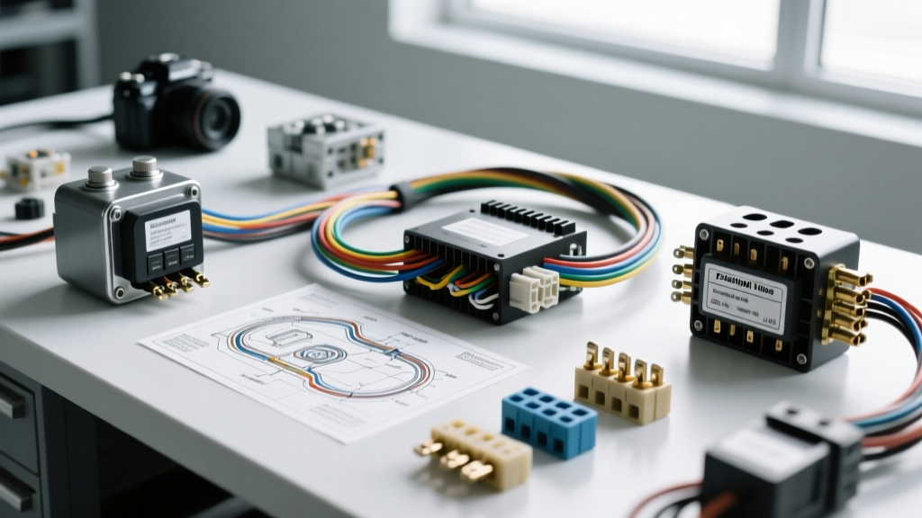
Upgrading Your Rig: Integrating Auxiliary Auto Electrical Components
Modern factory wiring harnesses are engineered with precise amperage limits designed specifically for original equipment manufacturer (OEM) specifications. When you begin adding high-draw aftermarket accessories—such as LED light bars, onboard air compressors, or dual-battery management systems—the stock harness simply cannot handle the thermal and electrical load. Attempting to splice high-amperage accessories directly into factory circuits is a primary cause of melted insulation, voltage drop, and catastrophic electrical fires. To safely integrate new auto electrical components into your vehicle, you must build a dedicated auxiliary circuit utilizing heavy-duty relays, marine-grade fuse blocks, and properly sized automotive wire.
This comprehensive installation guide details the exact methodology for wiring an auxiliary fuse block and relay bank. By treating your aftermarket accessories as independent auto electrical components that draw power directly from the battery and are merely triggered by the factory ignition switch, you preserve the integrity of your vehicle's CAN bus and body control module (BCM) while ensuring maximum voltage delivery to your accessories.
Essential Auto Electrical Components for Auxiliary Circuits
Before cutting a single wire, you must procure the correct materials. Standard hardware store wire and household crimp connectors will fail under the hood due to extreme heat, vibration, and chemical exposure. When selecting auto electrical components, adhere to the following specifications:
1. Automotive Wire (SAE J1128 GXL or TXL)
Never use THHN building wire or copper-clad aluminum (CCA) wire in a vehicle. You must use stranded copper wire that meets SAE J1128 standards. GXL (General Cross-Linked) and TXL (Thin-wall Cross-Linked) wires feature a cross-linked polyethylene (XLPE) insulation that can withstand continuous under-hood temperatures up to 125°C (257°F) and resist battery acid and oil. For marine or off-road environments, specify tinned copper to prevent sub-surface oxidation.
2. The Fuse Block and Main Overcurrent Protection
A sealed, marine-grade fuse block (such as the Blue Sea Systems ST Blade) provides a centralized, moisture-resistant location for your accessory fuses. The main power feed to this fuse block must be protected by a high-amperage Class T or ANL fuse mounted within 7 inches of the positive battery terminal to prevent an unfused dead-short in the event of a collision.
3. ISO Mini Relays and Flyback Diodes
Bosch-style ISO Mini relays are the industry standard for switching high-current loads. When selecting relays, opt for units with an integrated 1N4001 flyback diode. When a relay coil is de-energized, it generates a high-voltage inductive kickback (often exceeding 100V) that can destroy the delicate solid-state transistors in your vehicle's BCM or ignition switch. The flyback diode safely recirculates this spike.
ISO Mini Relay Pinout and AWG Specification Chart
Understanding the standard 4-pin/5-pin ISO relay layout is critical for correctly wiring your auto electrical components. Below is the definitive pinout and wire gauge specification chart for a standard 30A/40A ISO Mini relay.
| Pin Number | Function | Circuit Type | Recommended AWG | Standard Wire Color |
|---|---|---|---|---|
| 30 | Common Input (Power In) | Load (High Current) | 10 AWG | Red (12V+ from Fuse Block) |
| 87 | Normally Open (Power Out) | Load (High Current) | 10 AWG | Red (12V+ to Accessory) |
| 85 | Coil Ground | Control (Low Current) | 16 AWG | Black (Chassis Ground) |
| 86 | Coil Trigger (Power In) | Control (Low Current) | 16 AWG | Yellow (Switched 12V+ from Ignition) |
Note: Pin 87a (Normally Closed) is omitted on standard 4-pin relays. If using a 5-pin relay for winch solenoid control, ensure the relay is rated for the specific directional load.
Step-by-Step Installation Guide
Step 1: Routing the Main 4 AWG Power Feed
Disconnect the negative battery terminal and isolate it. Measure the distance from the positive battery terminal to your planned auxiliary fuse block location, adding 18 inches for routing slack and service loops. Cut a length of 4 AWG GXL red wire. Crimp a 3/8-inch adhesive-lined heat-shrink ring terminal on the battery end and a 5/16-inch ring terminal for the fuse block busbar.
Install a 100A ANL fuse holder on the positive battery post. Route the 4 AWG wire through the firewall using an existing rubber grommet—never drill a new hole without a protective grommet and silicone sealant. Secure the wire every 12 inches using UV-resistant nylon cable ties and protective split loom where the wire passes near sharp sheet metal or exhaust components.
Step 2: Establishing a True Chassis Ground
A poor ground is the root cause of 90% of all automotive electrical failures. Do not simply bolt your auxiliary ground busbar to painted sheet metal. Locate a heavy structural point on the chassis or engine block. Use a wire brush or sanding disc to remove all paint, powder coat, and rust down to bare, shiny metal.
Apply a small amount of anti-oxidant paste (such as Noalox) to the bare metal to prevent future galvanic corrosion, then secure the ground ring terminal using a Grade 8 flange bolt and a star washer to bite into the metal. Torque the bolt to the manufacturer's specification (typically 25-35 Nm for 3/8-inch chassis hardware). Run a 4 AWG black wire from this ground point directly to your auxiliary negative busbar.
Step 3: Wiring the Control (Trigger) Circuit
To ensure your auto electrical components turn off when you exit the vehicle, the relay coils (Pin 86) must be triggered by an ignition-switched circuit. Do not tap into the factory headlight or fuel pump wires. Instead, use a high-quality 'Add-A-Circuit' fuse tap in the interior cabin fuse box.
Locate a 10A or 15A ignition-switched circuit (like the windshield wipers or 12V accessory socket) using a digital multimeter. Install the Add-A-Circuit with a 5A Mini fuse to protect your 16 AWG trigger wire. Route the 16 AWG yellow trigger wire through the firewall to the relay bank. Connect this wire to Pin 86 on all your ISO relays using solder-seal heat shrink butt connectors. Finally, wire Pin 85 on all relays to your auxiliary negative busbar using 16 AWG black wire.
Step 4: Terminating the Load Circuit with Deutsch Connectors
From the auxiliary fuse block, run 10 AWG red wire to Pin 30 of your relay. From Pin 87, run 10 AWG red wire out to your accessory.
At the accessory end, avoid using cheap vinyl crimp connectors or exposed spade terminals, which will wick moisture and turn green with corrosion. Instead, terminate the wires using Deutsch DT series connectors. These thermoplastic housings feature silicone rear seals and wedge-locks that make them entirely waterproof and vibration-proof. Use a proper Deutsch crimp tool (such as the TE Connectivity DEUTSCH DT crimping pliers) to ensure a gas-tight crimp on the solid copper pins. Wrap the final connection in self-amalgamating silicone tape for secondary environmental protection.
Voltage Drop Testing and Troubleshooting
Once all auto electrical components are wired and the battery is reconnected, you must verify the circuit's efficiency using a voltage drop test. According to Blue Sea Systems engineering guidelines and standard automotive diagnostic procedures, a healthy high-current load circuit should exhibit no more than a 0.5V drop across the entire length of the wire and connections under full load. The control (trigger) circuit should show no more than a 0.1V drop.
How to Perform the Test:
- Set your multimeter to DC Volts.
- Activate the accessory so the relay clicks and current flows.
- Place the red probe on the positive battery terminal and the black probe on the positive input terminal of the accessory.
- Read the display. If your battery is at 12.6V and the accessory sees 12.4V, your voltage drop is a highly acceptable 0.2V.
- Repeat for ground: Place the red probe on the accessory's negative terminal and the black probe on the negative battery terminal. A reading over 0.3V indicates a corroded chassis ground or an undersized ground wire.
Common Failure Modes in Aftermarket Wiring
- Relay Chatter: If the relay rapidly clicks on and off, you likely have excessive voltage drop on the 16 AWG trigger wire, causing the coil voltage to fall below the holding threshold. Upgrade the trigger wire to 14 AWG or clean your ignition switch contacts.
- Melted Fuse Block Busbars: This occurs when cheap, tin-plated brass busbars are used instead of nickel-plated copper. Always verify that your chosen fuse block utilizes solid copper busbars capable of handling the cumulative amperage of all installed auto electrical components.
- Thermal Runaway in Connectors: If a Deutsch connector or ring terminal is warm to the touch after 10 minutes of operation, the crimp was poorly executed, creating high resistance. Cut the terminal off and re-crimp using a calibrated ratcheting tool.
Final Inspection and Safety Protocols
Integrating auxiliary auto electrical components requires a meticulous approach to overcurrent protection. Verify that every individual accessory wire is protected by an appropriately sized ATO or MINI fuse located within 18 inches of the auxiliary fuse block busbar. For a 30A relay circuit powering a 22A LED light bar, install a 25A fuse to protect the 10 AWG wire while accommodating transient startup spikes. For further reading on automotive fuse blow characteristics and time-delay curves, consult the Littelfuse Automotive Fuse Datasheets.
By adhering to SAE wire standards, utilizing flyback-protected ISO relays, and executing gas-tight crimps with marine-grade materials, your auxiliary electrical system will provide reliable, fire-free service in the harshest off-road and daily driving environments.