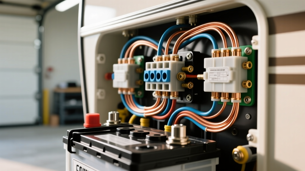
The Danger of Misinterpreting a Motorhome Battery Wiring Diagram
When upgrading or troubleshooting a Class A, B, or C motorhome, relying on a generic motorhome battery wiring diagram without understanding RV-specific electrical standards is a recipe for catastrophic failure. Unlike standard passenger vehicles, motorhomes feature a split electrical architecture: the 12V DC chassis system (starting battery) and the 12V DC house system (coach batteries), often bridged by a Battery Isolator Relay Device (BIRD). Mistakes in high-current DC wiring do not just cause a dead battery; they cause electrical fires, melted insulation, and destroyed alternators. Below are the most critical wiring mistakes and safety warnings every RV owner and technician must heed.
6 Costly Wiring Mistakes and Safety Warnings
1. Confusing SAE and RVIA Wire Color Codes
One of the most dangerous mistakes occurs when automotive mechanics apply standard SAE J1128 color codes to an RV. In standard automotive wiring, Black is universally used for 12V DC ground. However, the Recreational Vehicle Industry Association (RVIA) strictly dictates that White is used for 12V DC negative/ground, and Red is used for 12V DC positive. In an RV, Black wire is typically reserved for 120V AC hot lines or switched 12V DC accessory feeds. Using black wire for a high-amperage DC ground bus in a motorhome creates lethal confusion for future technicians and can lead to a direct 120V AC to 12V DC short if misidentified during an inverter installation. Always verify your specific motorhome battery wiring diagram against RVIA standards, not automotive assumptions.
2. Upgrading to Lithium Without Alternator Protection
Many owners use a basic motorhome battery wiring diagram to swap lead-acid house batteries for LiFePO4 (Lithium Iron Phosphate) banks. Because lithium batteries have extremely low internal resistance, a depleted 400Ah lithium bank connected via a standard BIRD solenoid will pull the maximum output of the chassis alternator continuously. A standard 150A automotive alternator is not designed for a 100% duty cycle and will overheat, melt the internal stator windings, and fail within hours. To prevent this, you must install a DC-DC charger (such as the Victron Orion-Tr Smart) or an Alternator Protection Module (APM) that limits current draw to 50-70% of the alternator's rated output.
3. Using ANL Fuses on Large Lithium Banks (AIC Failure)
A standard motorhome battery wiring diagram will often specify an ANL fuse for the main battery cutoff. While an ANL fuse is adequate for lead-acid batteries, it is a severe safety hazard for large lithium banks. Lithium batteries can deliver upwards of 5,000 to 10,000 amps in a dead short circuit. Standard ANL fuses have an Ampere Interrupting Capacity (AIC) of roughly 2,700 amps. If a massive short occurs, the ANL fuse element will vaporize, but it will fail to extinguish the resulting electrical arc, sustaining a plasma fire that can melt the fuse holder and ignite the surrounding cabinetry. For lithium banks exceeding 200Ah, you must use Class T fuses (20,000 AIC) or NH fuse strips.
4. Undersizing the BIRD Solenoid Cables
The BIRD (Battery Isolator Relay Device) bridges the chassis and house batteries when the engine is running. A common error is using 4 AWG or 2 AWG wire for this circuit based on the physical size of the solenoid terminals. If the run from the chassis battery to the BIRD solenoid, and then to the house battery, exceeds 15 feet, 4 AWG wire will suffer from severe voltage drop. At 100 amps of charging current, this voltage drop prevents the house bank from reaching absorption voltage and causes the solenoid to chatter or overheat. High-current bridging requires 2/0 AWG fine-stranded copper cable to minimize resistance and ensure the house bank receives adequate charging voltage.
5. Daisychaining High-Current Grounds to the Chassis
Automotive diagrams often show grounds attached directly to the nearest chassis frame bolt. In a motorhome, the chassis frame is subject to flex, rust, and poor conductivity across painted joints. Daisychaining multiple high-current DC loads (like an inverter and a water pump) to a single frame point creates ground loops, voltage offsets, and erratic sensor behavior. Proper RV electrical design requires a star grounding system. All major DC negative cables should route to a dedicated, insulated copper ground busbar. The busbar is then connected to the chassis frame using a single, massive 2/0 AWG ground strap, bolted to bare metal treated with Noalox anti-oxidant paste to prevent galvanic corrosion.
6. Soldering High-Current Battery Terminals
Soldering battery lugs is a relic of low-current electronics. In a high-vibration, high-current motorhome environment, solder wicks into the copper wire strands via capillary action, creating a rigid, brittle point just behind the lug. Under chassis vibration, this rigid point acts as a fulcrum, causing the copper strands to work-harden and eventually snap, leading to high-resistance arcing. The only acceptable method for terminating 4 AWG and larger battery cables is using a hex-crimp tool (producing a 6-sided compression) followed by sealing the barrel with 3M MDT adhesive-lined heat shrink to block moisture and battery acid fumes.
RV Battery Cable Sizing and Voltage Drop Chart
The following table outlines the maximum continuous amperage for 12V DC copper cable runs while maintaining a strict 3% maximum voltage drop (0.36V), as recommended by Victron Energy Wiring Unlimited Guidelines. Always measure the total round-trip distance (positive + negative) when calculating cable length.
| Wire Gauge (AWG) | Max Amps (10 ft Total Run) | Max Amps (20 ft Total Run) | Max Amps (30 ft Total Run) | Typical Application |
|---|---|---|---|---|
| 4 AWG | 60A | 30A | 20A | DC-DC Chargers, Slide-out Motors |
| 2 AWG | 95A | 48A | 32A | Solar Charge Controllers, Mid-Inverters |
| 1/0 AWG | 150A | 75A | 50A | 2000W Inverters, BIRD Circuits |
| 2/0 AWG | 190A | 95A | 63A | 3000W Inverters, Main Battery Banks |
| 4/0 AWG | 300A | 150A | 100A | Heavy Lithium Banks, Parallel Inverters |
Essential Safety Protocols and Torque Specifications
Working on a motorhome battery wiring diagram involves handling massive amounts of stored DC energy. A dropped wrench across a 4/0 AWG positive terminal and the chassis frame will instantly weld the metal, melt the wrench, and cause severe burns. Follow these non-negotiable safety protocols:
- Disconnect Sequence: ALWAYS disconnect the chassis negative first, then the house negative. When reconnecting, connect house positive, chassis positive, chassis negative, and house negative last.
- Insulated Tools: Only use VDE-certified 1000V insulated wrenches and sockets. Standard chrome vanadium tools offer zero protection against DC arcing.
- Terminal Torque Specs: Overtightening battery terminals strips the soft copper or aluminum busbars, while undertightening causes high-resistance hot spots. For M8 (8mm) terminal studs commonly found on LiFePO4 batteries, the maximum torque is 5 to 7 Nm (4.4 to 6.2 lb-ft). For M10 (10mm) studs on heavy-duty lead-acid or large lithium banks, torque to 10 to 12 Nm (7.4 to 8.8 lb-ft). Always use a calibrated inch-pound torque wrench.
- Compliance: Ensure all 12V DC and 120V AC wiring separation meets the minimum clearance requirements outlined in NFPA 1192 (Standard on Recreational Vehicles) to prevent inductive interference and thermal transfer.
Conclusion
A motorhome battery wiring diagram is only as safe as the technician executing it. By respecting RVIA color codes, calculating voltage drop accurately, utilizing Class T fuses for lithium banks, and employing proper hex-crimping techniques, you ensure your RV's electrical system is both reliable and fire-safe. For further reading on RV electrical standards and certification requirements, consult the RVIA Standards Database before initiating any high-current modifications.