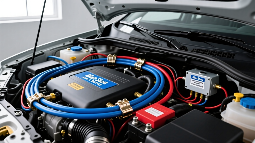
The Architecture of the Blue Sea Add-A-Battery System
When executing a high-current dual battery upgrade for overlanding, winching, or auxiliary lighting, relying on a simple diode isolator or manual switching is a recipe for stranded vehicles and dead starting banks. The industry standard for reliable power distribution is the Blue Sea Systems Add-A-Battery architecture. At the heart of this modification is the integration of a 1-2-BOTH-OFF battery switch with an Automatic Charging Relay (ACR), specifically the Blue Sea 7610 or 7622 Mini ACR. This guide provides a comprehensive breakdown of the blue sea add a battery wiring diagram, detailing the exact AWG requirements, routing protocols, and termination standards necessary to pass rigorous SAE and ABYC electrical inspections.
Unlike solid-state isolators that introduce a 0.6V to 1.0V voltage drop across their diodes, the Blue Sea ACR utilizes a heavy-duty internal contactor. When the system detects a charging voltage (typically 13.0V for two minutes or 13.6V for 30 seconds), the contactor closes, paralleling the starting and house battery banks with virtually zero voltage drop. When the engine stops and voltage falls below 12.75V for 30 seconds, the ACR opens, isolating the banks and ensuring your starting battery retains enough cold cranking amps (CCA) to fire the engine.
Component Manifest & Wire Gauge Specifications
Before cutting any cable, verify your bill of materials. The following table outlines the core components required for a standard 200A to 250A alternator dual-battery setup.
| Component | Part Number / Spec | Wire Gauge | Primary Function |
|---|---|---|---|
| 1-2-BOTH-OFF Switch | Blue Sea 5511e (ST Series) | 1/0 AWG | Main battery selection and emergency parallel |
| Automatic Charging Relay | Blue Sea 7610 ACR | 1/0 AWG (Feed) / 16 AWG (Sense) | Automatic bank paralleling during charge cycles |
| Main Overcurrent Protection | Class T Fuse Block (250A) | 1/0 AWG | Short circuit protection within 7 inches of battery |
| High-Current Lugs | 3/8 inch Ring Terminals | 1/0 AWG | Termination to busbars and switch studs |
| ACR Sense Wiring | Primary Wire (Yellow/Black/Green) | 16 AWG | Ignition sense, ground, and LED indicator |
Executing the Wiring Diagram: High-Current Routing
Phase 1: Battery to Switch Integration
The foundational layer of the blue sea add a battery wiring diagram involves routing the 1/0 AWG positive cables from both battery banks to the battery switch. According to SAE J1171 standards for marine and off-road electrical systems, any ungrounded conductor within 7 inches of the battery positive terminal must be protected by an overcurrent device. Therefore, a 250A Class T fuse must be installed on the positive cable of Battery 1 (Starting) and Battery 2 (House/Auxiliary) immediately adjacent to the battery post.
Route the fused 1/0 AWG red cable from Battery 1 to the '1' stud on the Blue Sea 5511e switch. Route the fused 1/0 AWG red cable from Battery 2 to the '2' stud. The common output stud on the switch will feed your vehicle's main starter solenoid and primary distribution busbar. Never route high-current DC cables parallel to sensitive CAN-bus or ECU wiring to prevent electromagnetic interference (EMI).
Phase 2: ACR Parallel Integration
The ACR is wired in parallel with the battery switch to allow automatic charging without manual intervention. Connect a 1/0 AWG cable from the '1' stud (or Battery 1 side of the main fuse) to the ACR's 'A' terminal. Connect a second 1/0 AWG cable from the '2' stud (or Battery 2 side) to the ACR's 'B' terminal. This configuration ensures that when the alternator outputs 14.2V, the ACR bridges the connection, sending current to the secondary battery bank.
ACR Sense and Control Wiring Protocols
The 7610 ACR features a secondary terminal strip for 16 AWG control wires. Proper execution of this low-current wiring is where most modification projects fail.
- Ignition Sense (Yellow Wire): Connect this to an ignition-switched 12V source. When the ignition is OFF, the ACR requires a higher voltage threshold (13.6V) to combine, preventing false triggers from solar surface charges. When the ignition is ON, it lowers the threshold to 13.0V. Crucially, this wire also prevents the ACR from engaging during engine cranking, avoiding massive voltage sags that can reset ECUs.
- Ground (Black Wire): Route this to a dedicated, cleaned chassis ground or a negative busbar. Do not daisy-chain this ground with high-draw accessories like inverters or fridges.
- LED Indicator (Green Wire): Connect to a dashboard-mounted Blue Sea LED indicator to provide visual confirmation of the ACR's combine/separate status.
Crimping, Termination, and Torque Specifications
A wiring diagram is only as reliable as its physical terminations. For 1/0 AWG high-current cables, use only adhesive-lined marine-grade heat shrink lugs (e.g., Ancor or 3M). The adhesive lining melts during the heat-shrinking process, creating a watertight seal that prevents copper oxidation and subsequent resistance buildup. Use a calibrated hex-crimp tool or a hydraulic crimper; never rely on hammer-style crimpers for primary battery feeds, as they often deform the barrel and create internal voids.
When securing the 3/8-inch lugs to the Blue Sea switch and ACR studs, apply a thin layer of dielectric grease to the threads and contact surfaces. Torque the hardware to exactly 120 in-lbs (10 ft-lbs). Under-torquing leads to micro-arcing and melted plastic housings, while over-torquing can strip the stainless steel studs or crack the glass-filled nylon bases.
Voltage Drop & Cable Length Reference Chart
Sizing your 1/0 AWG cables correctly based on the physical distance between the batteries and the switch is critical. Refer to standard copper ampacity charts to verify capacity. The table below illustrates expected voltage drop at a sustained 150A charging load.
| Total Cable Length (Round Trip) | 1/0 AWG Voltage Drop @ 150A | 2/0 AWG Voltage Drop @ 150A | Acceptability |
|---|---|---|---|
| 5 Feet | 0.23V | 0.18V | Excellent |
| 10 Feet | 0.46V | 0.36V | Acceptable |
| 15 Feet | 0.69V | 0.55V | Marginal (Upgrade to 2/0) |
| 20 Feet | 0.92V | 0.73V | Unacceptable (Risk of undercharging) |
Real-World Troubleshooting & Failure Modes
Even with a perfect blue sea add a battery wiring diagram, environmental factors and alternator quirks can cause operational anomalies. Below is a diagnostic decision tree for common dual-battery failure modes.
Symptom: ACR Rapidly Clicking (Chattering)
Cause: This occurs when the alternator cannot sustain the voltage threshold required to keep the ACR closed, often due to a high-draw accessory (like a winch or large inverter) pulling the system voltage down to 12.8V, causing the ACR to open, which removes the load, voltage spikes back to 13.2V, and the ACR closes again.
Fix: Verify the ignition sense wire is connected. If the issue persists, upgrade the alternator output or install a Blue Sea ML-ACR (Magnetic Latching ACR), which requires a pulse to change states rather than continuous voltage maintenance.
Symptom: House Bank Draining Starting Bank Overnight
Cause: The ACR is stuck in the closed position due to welded internal contacts (caused by hot-switching the battery bank under heavy load) or a short in the 16 AWG control wiring bypassing the internal logic board.
Fix: Disconnect the 16 AWG sense wires. If the ACR remains closed, the contactor is welded and the unit must be replaced. Never use the battery switch to break a heavy load; turn off all accessories before switching to 'OFF' to prevent inductive spikes that weld ACR contacts.
Authoritative References
For further reading on high-current DC distribution and overcurrent protection, consult the Blue Sea Systems Circuit Protection Guide. Always cross-reference your specific vehicle's CAN-bus topology before tapping into ignition sense circuits to avoid triggering ECU fault codes.