Understanding the Core Ebike Battery Wiring Diagram
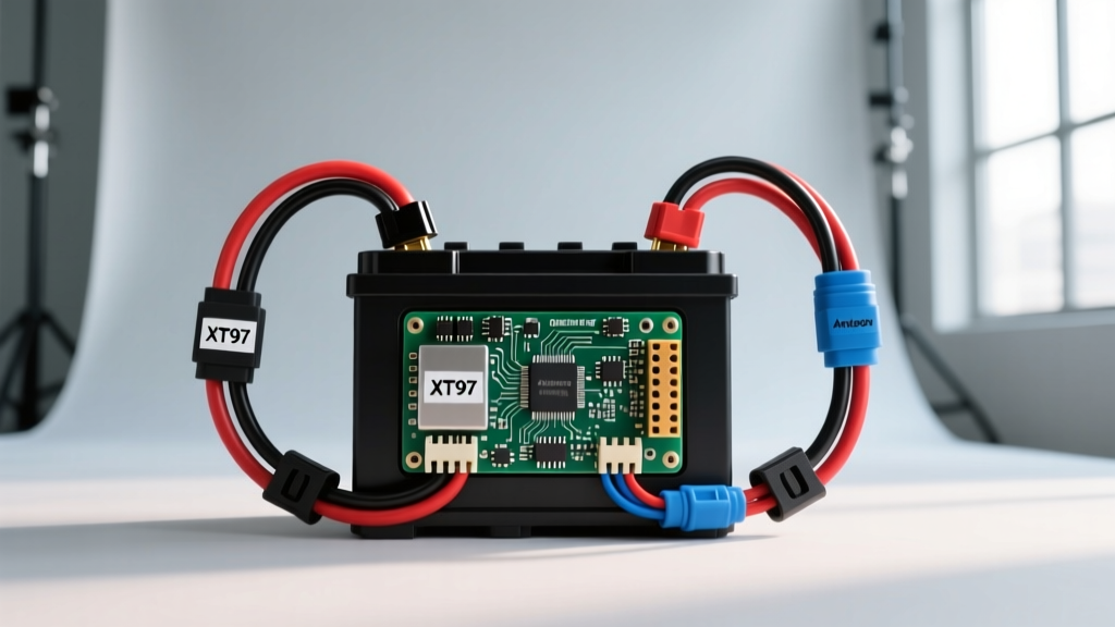
Designing a reliable 48V or 52V electric bicycle power system requires more than just matching positive and negative terminals. When consulting a comprehensive ebike battery wiring diagram, the architecture revolves around the Battery Management System (BMS), cell group balancing, and high-current discharge harnesses. Whether you are building a custom 13S (48V nominal) or 14S (52V nominal) lithium-ion pack using 18650 or 21700 cells, the wiring topology dictates your system's safety, thermal performance, and longevity.
In a standard high-current DC micro-mobility setup, the main positive (B+) flows directly from the cell pack to the controller's main power input. The main negative (B-) routes through the BMS before reaching the controller. This 'low-side switching' configuration allows the BMS to monitor current draw and disconnect the ground path during over-current, short-circuit, or under-voltage events. Understanding this flow is critical before selecting components, as improper routing can bypass safety mechanisms and lead to catastrophic thermal runaway.
BMS Topology Comparison: Common vs. Separate Port vs. Smart BMS
The BMS is the brain of your pack. Selecting the right topology changes how your charge and discharge circuits are wired. According to Battery University's BMS guidelines, proper cell balancing and current monitoring are non-negotiable for lithium-ion chemistries.
| BMS Type | Wiring Configuration | Max Continuous Current | Best Application |
|---|---|---|---|
| Common Port | Charge and Discharge share the same P- / P+ pads. | 30A - 60A | Standard commuter e-bikes, low-draw 500W-1000W hub motors. |
| Separate Port | Discharge uses P- pad; Charge uses dedicated C- pad. | 60A - 120A | High-performance builds, 1500W+ mid-drives requiring heavy discharge but standard 5A charging. |
| Smart BMS (UART/BLE) | Separate Port + Data lines for Bluetooth/Serial monitoring. | 100A - 250A+ | Custom builds requiring cell-level voltage logging, temp monitoring, and adjustable LVC/HVC. |
Wiring the Sense Harness: The BMS balance harness utilizes 22 AWG or 24 AWG stranded wire, typically terminated with a JST-SM or Molex 51021 connector. The black wire always solders to the main pack negative (B-). Subsequent wires (B1 through B13/B14) solder to the positive nickel strip of each respective cell group in sequential order. Never plug the sense harness into the BMS until all solder joints are verified with a multimeter; an out-of-sequence pin will instantly destroy the BMS logic board.
High-Current Connector Selection: XT60 vs. XT90 vs. Anderson SB
The connector on your main discharge harness is a primary failure point in any ebike battery wiring diagram. Vibration, moisture, and high amperage cause oxidation and resistance, leading to melted housings. Selecting the correct connector requires analyzing your controller's peak amp draw.
XT60 Connectors
- Rating: 60A continuous, 100A peak (10 seconds).
- Wire Compatibility: 10 AWG to 12 AWG silicone wire.
- Pros: Compact, widely available, polarized.
- Cons: Prone to 'spark damage' on the negative pin when connecting to a controller with large capacitors. Repeated arcing pits the brass contacts, increasing resistance and eventually melting the nylon housing.
XT90 / XT90-S (Anti-Spark)
- Rating: 90A continuous, 150A peak.
- Wire Compatibility: 8 AWG to 10 AWG silicone wire.
- Pros: The XT90-S variant includes a built-in resistor on one pin that pre-charges controller capacitors, eliminating connection sparks and preserving contact integrity.
- Cons: Bulkier than XT60; requires a larger battery enclosure exit hole.
Anderson Powerpole SB50
- Rating: 50A continuous, 120A peak (wire-to-wire).
- Wire Compatibility: 6 AWG to 10 AWG.
- Pros: Genderless housing, stainless steel leaf-spring contacts maintain constant pressure, preventing the connection loosening common in XT-series connectors. Highly resistant to vibration. Refer to the Anderson Power SB50 Datasheet for exact derating curves.
- Cons: Requires specialized crimping tools or careful soldering; not inherently water-resistant without a boot.
Wire Gauge (AWG) & Silicone Jacket Selection
Automotive and micro-mobility standards dictate that wire sizing must account for continuous current, not just peak current. While SAE J1127 outlines standards for heavy-duty battery cables, e-bike applications require ultra-flexible silicone-jacketed wire to withstand frame vibration and tight enclosure bends without copper strand fatigue.
- 12 AWG (Silicone): Rated for ~40A continuous. Suitable for 250W-500W systems drawing under 20A continuous.
- 10 AWG (Silicone): Rated for ~55A continuous. The standard for most 48V 1000W-1500W hub motor builds. Features approx. 1050 strands of 0.08mm tinned copper.
- 8 AWG (Silicone): Rated for ~75A continuous. Mandatory for 52V systems pushing 1500W-2500W mid-drive or direct-drive setups. Use 8 AWG for the internal BMS to pack wiring, and step down to 10 AWG only if the external harness to the controller is under 18 inches.
Expert Tip: Always use tinned copper wire. Bare copper oxidizes rapidly in high-humidity environments, leading to increased resistance and voltage sag under heavy throttle loads.
Step-by-Step Harness Routing & Soldering Best Practices
- Prep the Pads: Flux the BMS P- and B+ pads. Pre-tin them with 60/40 rosin-core solder. Do not use acid-core plumbing solder, as it will corrode the copper traces.
- Stripping & Tinning: Strip 8mm of 10 AWG silicone wire. Twist the strands tightly, apply liquid flux, and tin the wire until the solder wicks entirely through the strands.
- Thermal Management: Use a minimum 150W temperature-controlled soldering station. A low-wattage iron will linger on the BMS pad, transferring excessive heat and potentially delaminating the internal MOSFETs or lifting the PCB trace.
- Strain Relief: Once soldered, apply a bead of neutral-cure RTV silicone (not acetic acid silicone, which eats copper) over the solder joints. Use heat shrink tubing with an inner layer of adhesive-lined marine shrink to seal the exit point of the battery case.
Troubleshooting Common Voltage Drop & BMS Cut-off Failures
Even with a perfect ebike battery wiring diagram on paper, physical execution often introduces faults. Here is a diagnostic decision tree for common high-current failures:
- Symptom: Controller shuts off under heavy throttle, but battery voltage reads full when resting.
Cause: Voltage sag due to undersized wiring or a weak cell group.
Fix: Measure voltage at the controller pins under load. If it drops below the LVC (Low Voltage Cutoff, typically 40V for a 48V system), check the BMS sense wires for high resistance. A loose B12 sense wire will cause the BMS to read a false low-voltage on that cell group and trigger an early cutoff. - Symptom: XT60 connector housing is melted or deformed.
Cause: Contact resistance from arcing or vibration-induced loosening.
Fix: Cut off the XT60. Upgrade the harness to an XT90-S or Anderson SB50. Ensure the controller side uses the male pins (with the exposed prongs) and the battery side uses the female housing to prevent accidental shorting. - Symptom: Battery will not charge, but discharges fine.
Cause: If using a Separate Port BMS, the charge circuit MOSFET may be blown, or the C- pad solder joint has fractured.
Fix: Test continuity between the charge port negative and the BMS C- pad. If open, reflow the solder joint. If the joint is solid, the BMS charge MOSFET is likely damaged and the BMS must be replaced.
By meticulously following component selection guidelines and adhering to high-current DC wiring standards, you ensure your e-bike power system delivers maximum efficiency without compromising safety.