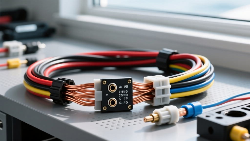
Introduction: Why Marine Audio Wiring Demands Precision
Installing an aftermarket head unit and amplifier on a vessel is fundamentally different from a standard car audio installation. When consulting a boat stereo wiring diagram, you are not just managing 12-volt DC power and audio signals; you are battling a highly corrosive saltwater environment, constant high-frequency vibration, and strict maritime safety standards. The American Boat & Yacht Council (ABYC) standard E-11 dictates rigorous requirements for DC electrical systems on boats to prevent galvanic corrosion, capillary wicking, and electrical fires. This practical how-to guide will walk you through decoding your marine stereo wiring diagram, selecting the correct UL 1426 tinned copper wire, and executing waterproof terminations that will survive the harshest marine conditions.
The Great Color Code Conflict: ABYC vs. EIA/CEA Standards
The most dangerous trap when reading a boat stereo wiring diagram is the conflict between marine electrical standards and consumer electronics standards. If you blindly connect wires based on color alone, you risk a dead short that could melt your wiring harness or start a fire behind the helm.
Decoding the Stereo Side (EIA/CEA Standard)
Aftermarket marine stereos (from brands like Fusion, JL Audio, and Clarion) use the standard Consumer Technology Association color codes for their pigtail harnesses:
- Yellow: +12V Constant (Memory/ECU)
- Red: +12V Switched (Ignition/Accessory)
- Black: DC Ground (Negative)
- Orange/White: Illumination/Dimmer
Decoding the Boat Side (ABYC E-11 Standard)
However, the DC wiring harness native to your boat's helm likely follows ABYC color codes, where the colors mean something entirely different:
- Yellow or Yellow with Stripe: DC Negative (Ground)
- Red: DC Positive (Unfused or Main Battery feed)
- Black: AC Hot (Shore Power) or sometimes DC Positive in older rigs
Critical Warning: If you connect the stereo's Yellow (+12V Constant) wire to the boat's Yellow (DC Negative/Ground) wire, you will create a direct short circuit the moment the battery is connected. Always use a multimeter to verify the boat's harness polarity before making any connections, regardless of the wire colors.
Standard Marine Head Unit Pinout and Connection Table
When splicing your aftermarket stereo pigtail to the vessel's DC bus or switch panel, use the following reference matrix. Always route your stereo's ground wire to a dedicated, waterproof bus bar rather than relying on the aluminum or fiberglass dash structure for grounding.
| Stereo Wire Color | Function | Marine Connection Target | Recommended AWG |
|---|---|---|---|
| Yellow | +12V Constant Memory | Always-on DC Bus (Fused) | 14 AWG |
| Red | +12V Switched (ACC) | Helm Ignition / ACC Switch Panel | 14 AWG |
| Black | DC Ground | Negative Shunt / DC Bus Bar | 14 AWG |
| Orange | Illumination | Helm Light Dimmer Circuit | 18 AWG |
| Blue/White | Amp Turn-On | Amplifier Remote Terminal | 18 AWG |
Step-by-Step Marine Stereo Installation Guide
Follow these steps to ensure your installation meets the rigorous demands of the marine environment, as outlined by experts at Marine How-To.
Step 1: Isolate the DC Power
Disconnect the main negative battery cable at the house bank. Never work on a live marine DC system. Verify zero voltage at the helm using a digital multimeter before cutting or stripping any existing wires.
Step 2: Select the Correct Marine-Grade Wire
Never use standard automotive copper wire (SAE J1128) in a boat. Automotive wire is untinned and will rapidly oxidize, turning black and increasing resistance. You must use UL 1426 / SAE J1128 Type III Boat Cable. This wire features individually tinned copper strands to prevent galvanic corrosion and capillary wicking (where water travels up the wire jacket and into the stereo).
Step 3: Execute Waterproof Terminations
Solder alone is prohibited by ABYC for high-vibration environments because it creates a brittle joint that can snap under the constant pounding of ocean waves. Instead, use adhesive-lined heat shrink crimp connectors. Strip the wire, insert it into the tinned brass barrel of the connector, and crimp using a ratcheting crimper. Apply heat evenly until the connector shrinks tightly and the inner adhesive oozes out both ends, creating a 100% waterproof seal.
Step 4: Install the Primary Fuse (MRBF)
According to ABYC E-11, any positive wire connected directly to the battery must be fused within 7 inches of the terminal. Install a Marine Rated Battery Fuse (MRBF) or a Class T fuse block directly on the positive battery post to protect the main power feed running to your helm and audio amplifiers.
Step 5: Route Signal and Power Cables Separately
Marine engines and alternators generate massive electromagnetic interference (EMI). To prevent alternator whine in your speakers, route your RCA signal cables and amplifier turn-on wires at least 18 inches away from any high-current 12V power cables or engine ignition wiring.
Amplifier Integration and ABYC AWG Sizing Chart
Adding marine amplifiers to power tower speakers and subwoofers requires heavy-gauge power delivery. Because voltage drop over long cable runs (from the transom battery to the tower amps) can starve your amplifiers and trigger protection modes, you must size your wire according to ABYC voltage drop tables (allowing a maximum 3% drop for critical electronics, or 10% for non-critical audio loads).
| Amplifier Max Current Draw | Run Length (One Way) | Required Boat Cable AWG | Fuse Rating (ANL) |
|---|---|---|---|
| 30 Amps | 10 Feet | 10 AWG | 40A |
| 30 Amps | 20 Feet | 8 AWG | 40A |
| 60 Amps | 10 Feet | 8 AWG | 70A |
| 60 Amps | 20 Feet | 4 AWG | 70A |
| 100+ Amps | 15 Feet | 1/0 AWG | 125A |
Note: Always use a dedicated positive and negative bus bar near the amplifier location to distribute power to multiple amps, rather than daisy-chaining power wires.
Waterproofing the Head Unit and Dash Connections
Even if you purchase an IPX6-rated marine head unit, the wiring harness connection at the rear of the chassis is a primary vulnerability. Moisture trapped inside the dash console will condense on the cool metal chassis and seep into the pin connections. After verifying all connections with a multimeter, apply a liberal coating of dielectric grease to the plastic Molex connectors before mating them. For the bare wire splices, wrap the entire harness in split loom tubing and seal the ends with marine-grade silicone sealant (such as 3M Marine Adhesive Sealant 5200 or 4200) to prevent humid air from entering the wire loom.
Troubleshooting Common Marine Audio Faults
When your newly installed marine stereo fails to power on or exhibits audio anomalies, use this diagnostic tree before tearing into the dash:
- Symptom: Stereo loses presets and clock every time the boat is turned off.
Cause: The Yellow (+12V Constant) wire is wired to a switched circuit, or the inline fuse on the memory wire has blown due to a voltage spike. Check the inline glass fuse on the stereo pigtail and verify continuous 12V at the yellow wire with the ignition OFF. - Symptom: High-pitched alternator whine that increases with engine RPM.
Cause: Ground loop or EMI induction. Ensure the head unit, amplifier, and RCA cables are all grounded to the exact same DC negative bus bar. Do not ground the amplifier to the engine block and the head unit to the helm dash. - Symptom: Amplifier goes into protect mode when hitting heavy bass.
Cause: Voltage drop due to undersized wire or corroded bus bar lugs. Measure the DC voltage directly at the amplifier's positive and negative terminals while playing bass. If it drops below 10.5V, upgrade your AWG wire size and clean the bus bar connections with a wire brush and contact cleaner.
Final Inspection and Commissioning
Before reconnecting the main battery bank, perform a final visual inspection of your boat stereo wiring diagram execution. Ensure no bare copper is exposed, all heat shrink seals are fully cured, and your MRBF main fuse is properly seated. Reconnect the negative battery cable, turn on the helm ignition, and verify that your head unit powers on, retains memory, and triggers your amplifiers cleanly. By adhering strictly to marine-grade materials and ABYC standards, your audio system will deliver pristine sound on the water for years without succumbing to the elements. For further engineering guidelines on marine audio setups, consult JL Audio's Marine Engineering Resources.