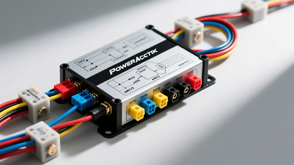
Demystifying the Power Acoustik Amp Wiring Diagram
Upgrading your vehicle's audio system is one of the most rewarding DIY automotive projects you can tackle, but the electrical foundation is where most beginners stumble. When you first unbox a new amplifier—especially high-output models from the BAMF or Gothic series—interpreting the Power Acoustik amp wiring diagram in the manual can feel overwhelming. You are suddenly confronted with heavy-gauge cables, set-screw terminal blocks, and strict routing rules.
As an automotive electrical specialist, I see countless installations fail not because of bad equipment, but due to improper wire sizing, poor grounding, and misunderstood terminal connections. This beginner-friendly fundamentals guide will break down the standard Power Acoustik amplifier wiring schematic into actionable, safe, and reliable steps. Whether you are running a modest 4-channel setup for component speakers or a monoblock class-D subwoofer amplifier, mastering these core electrical principles is mandatory for achieving clean sound and preventing vehicle fires.
Anatomy of a Power Acoustik Terminal Block
Unlike some European brands that use proprietary plug-in harnesses, Power Acoustik amplifiers typically utilize heavy-duty, set-screw terminal blocks. Understanding what each port demands is the first step in reading the wiring diagram correctly.
- B+ (Battery Positive): The main 12V power input. This requires heavy-gauge wire (usually 4 AWG to 1/0 AWG) routed directly from the vehicle's positive battery terminal through an inline fuse.
- B- or GND (Ground): The return path for the electrical circuit. This must be connected to bare, unpainted chassis metal within 3 feet of the amplifier.
- REM (Remote Turn-On): A low-current signal wire (18 AWG) that tells the amplifier's internal power supply to wake up when the stereo is turned on.
- Speaker Outputs / RCA Inputs: Depending on the model, you will either use standard RCA jacks for low-level signals or a plug-in harness for high-level (speaker wire) inputs.
Wire Gauge (AWG) & Length Matrix
The most critical mistake beginners make is underestimating current draw. Power Acoustik amplifiers, particularly the BAMF series, are designed for high-current delivery. Using undersized wire causes voltage drop, leading to thermal clipping, dimming headlights, and melted insulation. According to SAE J1128 Battery Cable Standards, you must size your wire based on the total RMS wattage and the total length of the cable run (from battery to amp, plus amp to ground).
| Total RMS Wattage | Cable Run (0-10 ft) | Cable Run (10-15 ft) | Cable Run (15-20 ft) | Recommended Inline Fuse |
|---|---|---|---|---|
| Up to 400W | 8 AWG | 8 AWG | 4 AWG | 40A AGU / ANL |
| 400W - 800W | 4 AWG | 4 AWG | 2 AWG | 80A ANL |
| 800W - 1500W | 2 AWG | 1/0 AWG | 1/0 AWG | 150A ANL / Mega |
| 1500W - 2500W+ | 1/0 AWG | 1/0 AWG | 2/0 AWG | 250A+ Mega Fuse |
Expert Note: Always invest in 100% Oxygen-Free Copper (OFC) wire. Copper-Clad Aluminum (CCA) wire has higher resistance and requires you to step up one AWG size to safely handle the same current load.
Step-by-Step Wiring Fundamentals
Follow this sequence to ensure a safe, noise-free installation. For a comprehensive visual overview, refer to Crutchfield's Amplifier Installation Guide, which pairs perfectly with the technical specs below.
Step 1: The Main Power Wire (B+)
Disconnect the negative terminal on your vehicle's battery before running any wire. Route your main OFC power cable from the battery, through the firewall (using an existing rubber grommet—never drill bare metal without a grommet), and down the vehicle's interior. Crucial Safety Rule: You must install an inline fuse holder on the positive power wire within 18 inches of the battery positive terminal. This fuse protects the entire vehicle from a dead short in the event of a collision or chafed wire; the fuse on the amplifier itself only protects the amp.
Step 2: Establishing a True Ground (B- / GND)
A poor ground is responsible for 90% of all car audio issues, including alternator whine, bass hitting weakly, and protect-mode triggering.
- Locate a thick, structural bolt on the vehicle chassis within 3 feet of the amplifier.
- Remove the bolt and use 80-grit sandpaper or a wire wheel to strip away all paint, primer, and clear coat down to bare, shiny steel.
- Crimp a heavy-duty, heat-shrink ring terminal onto your ground wire. Use a proper hex-crimp tool, not pliers.
- Secure the ring terminal to the bare metal. Apply a dab of anti-oxidant dielectric grease (like Noalox) over the connection to prevent rust from creeping under the terminal and increasing resistance over time.
Step 3: The Remote Turn-On Wire (REM)
The remote wire carries almost zero amperage (usually under 300mA). You can use standard 18 AWG primary wire for this. Connect one end to the Blue/White wire on your aftermarket head unit's wiring harness. Route this wire down the same side of the vehicle as your RCA signal cables (away from the main power wire) and insert it into the 'REM' set-screw on the Power Acoustik terminal block. If you are using a factory radio without an amplifier turn-on lead, you will need to tap into a 12V accessory fuse in the cabin fuse box using an Add-A-Circuit fuse tap, or use a dedicated remote turn-on module.
Signal Input Routing: RCA vs. High-Level
Power Acoustik amplifiers are versatile, often featuring both standard RCA jacks and high-level speaker wire inputs.
- Low-Level (RCA): If using an aftermarket stereo, run shielded RCA cables from the head unit to the amp. Never route RCA cables on the same side of the vehicle as the 12V power wire. The electromagnetic field generated by high current flowing through the power wire will induce a high-pitched whine into the unbalanced RCA shields. Run power down the driver's side, and RCA/Speaker wires down the passenger side.
- High-Level (Speaker Wire): If integrating with a factory amplifier or a basic radio without RCA outputs, use the included high-level wiring harness. Splice the harness into the factory speaker wires at the kick panels or rear deck. The amplifier's internal summing circuit will step the high-voltage speaker signal down to a usable line-level signal.
Troubleshooting Common Beginner Mistakes
Even with a perfect wiring diagram, physical execution errors happen. If your Power Acoustik amp isn't performing correctly, check these real-world failure modes:
The Amplifier Protection Light is Solid Red
Cause: Short circuit, severe voltage drop, or impedance mismatch. Fix: Check your speaker wire connections at the amplifier's set-screws. Beginners often strip stranded wire too far, allowing a single microscopic copper strand to escape the terminal block and touch the adjacent channel or the metal chassis. Trim the wire, re-twist, and ensure the set-screw is clamping down firmly on the copper, not the wire insulation.
Bass Drops Out at High Volume
Cause: Voltage starvation or thermal protection. Fix: Measure the voltage at the B+ and B- terminals on the amp while playing heavy bass. If the voltage drops below 10.5V, your wiring is too thin, your ground is poor, or your vehicle's alternator cannot keep up. For high-output BAMF monoblocks pulling over 1500W RMS, upgrading your vehicle's 'Big Three' wiring (Alternator to Battery, Engine to Chassis, Battery to Chassis) with 1/0 AWG OFC wire is highly recommended by the Mobile Electronics Certification Program (MECP).
Alternator Whine in the Speakers
Cause: Ground loop or EMI interference. Fix: Ensure the head unit and the amplifier share the same ground potential. If the RCA cables were run alongside the power wire, re-route them. If the whine persists, verify that your RCA cables are not damaged and that your amplifier's ground connection is completely free of paint and rust.
Final Torque and Safety Checks
Before reconnecting your vehicle's battery, perform a physical tug test on every wire entering the Power Acoustik terminal block. The set-screws on these amplifiers are made of brass; overtightening them with excessive force can strip the threads or snap the screw head. Tighten them firmly with a properly sized Allen key or flathead screwdriver until the wire cannot be pulled free, but avoid using mechanical impact drivers. Finally, double-check that your inline fuse matches the total amperage draw of your system, and ensure no bare wire is exposed outside the terminal blocks. With these fundamentals mastered, your Power Acoustik amplifier will deliver reliable, high-fidelity sound for years to come.