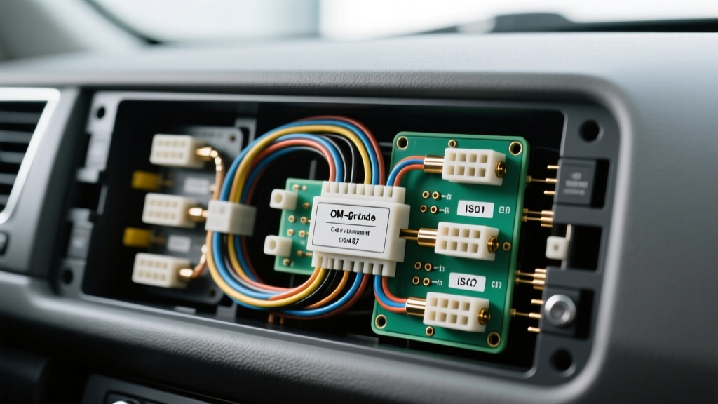
The Paradigm Shift: From ISO 10487 to Multiplexed Networks
When interpreting modern auto stereo wiring diagrams, technicians must abandon the simplistic 12V-ground-speaker paradigm of the 1990s. Today's infotainment systems are deeply embedded nodes on the vehicle's multiplexed data network. While the ISO 10487:2006 standard still dictates the baseline physical connector architecture for aftermarket head units—specifically the 8-pin Block A (power) and 8-pin Block B (speaker) configurations—OEM manufacturers have largely migrated to proprietary 28-pin, 44-pin, or 54-pin harnesses. These advanced diagrams do not merely show power routing; they map out high-speed data lanes, amplifier wake-up logic, and steering wheel control (SWC) resistance ladders.
Understanding these schematics requires a firm grasp of automotive network topologies. An installer who misinterprets a data line for a standard 12V accessory wire will not only fail to power on the aftermarket amplifier but risks catastrophic damage to the vehicle's Body Control Module (BCM). This guide provides an advanced technical deep dive into decoding modern auto stereo wiring diagrams, focusing on CAN-bus integration, OEM-to-ISO translation, and oscilloscope-level diagnostics.
Decoding CAN-Bus and GMLAN in Stereo Schematics
In modern wiring diagrams, you will frequently encounter twisted-pair data lines labeled as CAN-H (High) and CAN-L (Low), or in General Motors applications, GMLAN. Governed by the ISO 11898 standard, the Controller Area Network (CAN) bus allows the radio, amplifier, BCM, and instrument cluster to communicate without dedicated copper runs for every single function. According to CAN in Automation (CiA), this differential signaling is highly resistant to electromagnetic interference (EMI), which is critical in an environment saturated by alternator whine and high-current ignition pulses.
Differential Signaling and Impedance Matching
When a wiring diagram highlights a CAN-bus connection, it is indicating a differential voltage system. In a recessive state (logical 1), both CAN-H and CAN-L sit at approximately 2.5V. In a dominant state (logical 0), CAN-H rises to ~3.5V while CAN-L drops to ~1.5V. The receiving node reads the voltage difference.
Critical Warning: Never use T-taps or scotch locks to tap into CAN-H or CAN-L wires to trigger an aftermarket relay. Doing so alters the physical layer's impedance. The CAN network relies on 120-ohm termination resistors at each end of the bus. Piercing the wire insulation introduces capacitance and resistance variations that can reflect signals, causing network collisions and throwing U-codes (e.g., U0155 - Lost Communication With Instrument Panel Cluster).
| Network Protocol | Max Baud Rate | Dominant / Recessive Voltages | Typical OEM Wire Colors | Primary Audio Function |
|---|---|---|---|---|
| CAN-C (High Speed) | 1 Mbps | 3.5V / 1.5V (Diff: 2.0V) | Pink/White & Pink/Green (Chrysler) | Amplifier DSP data, BCM wake-up |
| GMLAN (GM) | 33.3 kbps / 83.3 kbps | 3.5V / 1.5V (Single Wire CAN) | Green & Green/White | Radio display, OnStar integration |
| LIN Bus | 20 kbps | 12V (Recessive) / 1V (Dominant) | Violet/White (Ford) | Steering Wheel Controls (SWC) |
| Class 2 (Legacy GM) | 10.4 kbps | 0V to 7V Pulsed | Dark Green | Chime routing, basic radio data |
The Disappearance of the 12V Remote Turn-On Wire
Historically, auto stereo wiring diagrams featured a dedicated blue or blue/white wire (ISO Block A, Pin 5) designated for the antenna motor or amplifier remote turn-on. In modern vehicles, this hardwired 12V trigger has been eliminated to reduce copper weight and parasitic draw. Instead, the OEM amplifier is woken up via a data message broadcast over the CAN-bus when the BCM detects the ignition cylinder in the 'ACC' or 'RUN' position.
Extracting Amplifier Logic from Data Streams
When installing an aftermarket DSP or high-current amplifier (requiring 4 AWG or 8 AWG power and a dedicated 30A+ remote relay), you cannot rely on a simple 12V tap. You must use a CAN-bus interface module (such as those documented in PAC Audio's technical repositories or the iDatalink Maestro RR). These modules read the OEM data packets, verify the ignition status, and synthesize a clean 12V, 500mA remote turn-on output. When reading the vehicle's schematic, locate the data link connector (DLC) pins 6 (CAN-H) and 14 (CAN-L), or trace the infotainment CAN lines directly from the back of the OEM radio harness to feed the interface module.
OEM Proprietary Connectors vs. Standard ISO Block A/B
Translating a factory schematic to an aftermarket ISO 10487 harness requires meticulous pin-by-pin mapping. Japanese and American manufacturers often combine power, ground, and speaker outputs into a single high-density block. Below is a technical translation table for a common Toyota 10-pin + 16-pin OEM harness to the standard ISO Block A and Block B format.
| OEM Pin (Toyota 10+16) | OEM Wire Color | Function | ISO 10487 Target | AWG / Spec Notes |
|---|---|---|---|---|
| 10-Pin: Pin 1 | White/Red | +B (Constant 12V) | Block A, Pin 4 (Yellow) | 16 AWG (High Current Memory) |
| 10-Pin: Pin 2 | Gray | ACC (Switched 12V) | Block A, Pin 7 (Red) | 18 AWG |
| 10-Pin: Pin 7 | Brown | GND (Chassis Ground) | Block A, Pin 8 (Black) | 16 AWG (Critical for SNR) |
| 10-Pin: Pin 6 | Blue/White | ANT / AMP Turn-On | Block A, Pin 5 (Blue) | 18 AWG (Max 300mA draw) |
| 16-Pin: Pin 3 | Pink | Front Left (+) | Block B, Pin 1 (White) | 18 AWG |
| 16-Pin: Pin 4 | Purple | Front Left (-) | Block B, Pin 2 (White/Black) | 18 AWG (Do not ground!) |
Technical Note on Speaker Grounds: In modern OEM diagrams, speaker negative wires are NOT chassis grounds. They are bridged outputs (BTL - Bridge-Tied Load) from the factory Class-D amplifier built into the head unit. Grounding an OEM speaker negative wire to the chassis will short-circuit the head unit's internal amplifier IC, triggering thermal protection or causing permanent silicon failure.
Advanced Diagnostics: Verifying Diagrams with an Oscilloscope
Wiring diagrams are theoretical representations; mid-year production changes, trim-level variations, and aftermarket modifications can render a schematic inaccurate. When a diagram fails to match the physical harness, advanced technicians rely on a Picoscope or high-end digital multimeter (DMM) to verify circuit behavior.
Symptom-Cause-Fix Decision Tree: CAN-Bus Integration Failures
- Symptom: Vehicle battery drains overnight (parasitic draw >50mA) after stereo installation.
Cause: Aftermarket interface module back-feeding voltage into the CAN-H line, preventing the BCM from entering sleep mode.
Fix: Verify interface module firmware; ensure the CAN-bus transceiver is properly isolated when the ignition is off. Check for pinched wires near the radio bracket. - Symptom: Alternator whine introduced into the audio signal immediately after tapping OEM speaker wires.
Cause: The OEM amplifier uses a common-ground or active noise cancellation (ANC) topology, and the aftermarket DSP is creating a ground loop.
Fix: Use an audio isolation transformer or a DSP with differential, isolated high-level inputs. Do not share the DSP ground with the OEM head unit ground. - Symptom: Radio powers on, but steering wheel controls (SWC) are unresponsive despite correct resistance ladder wiring.
Cause: The vehicle uses a LIN-bus or CAN-bus for SWC, not an analog resistance ladder (common in post-2015 Ford and Chrysler vehicles).
Fix: Abandon the analog SWC adapter. Route the LIN/CAN data wires to a digital data retention module capable of translating multiplexed button presses into analog resistance or direct CAN commands for the aftermarket radio.
Conclusion: Precision Over Assumption
Mastering advanced auto stereo wiring diagrams requires an understanding of automotive network architecture. By respecting ISO 11898 impedance requirements, accurately translating proprietary OEM pinouts to ISO 10487 standards, and utilizing oscilloscope diagnostics when schematics fall short, installers can achieve flawless, factory-grade integrations without compromising the vehicle's delicate electrical ecosystem.