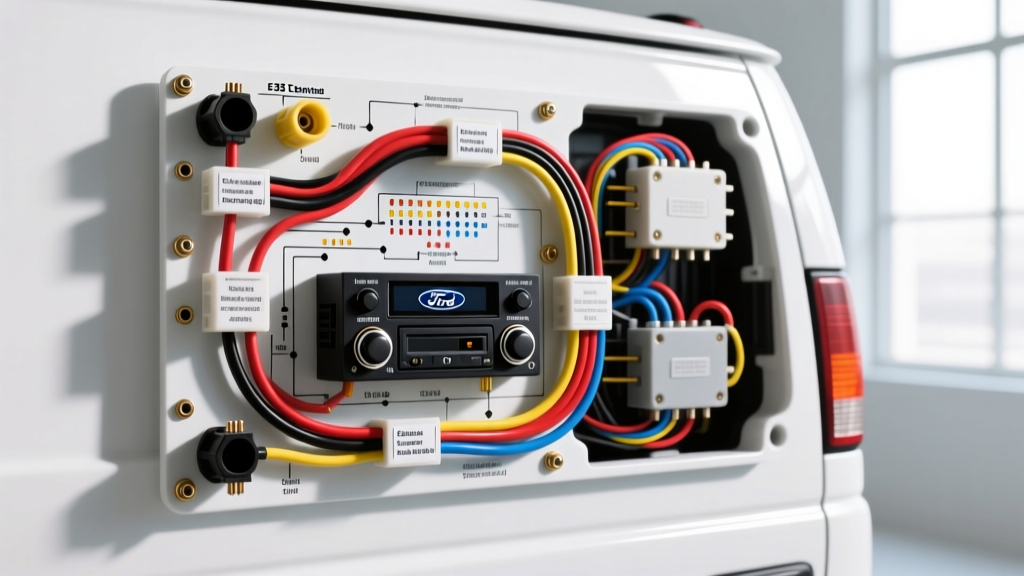
Introduction to the Ford E-350 Econoline Audio Platform
The Ford E-Series Econoline, particularly the E-350 cutaway and passenger van models produced between 1999 and 2014, represents one of the most enduring platforms in American automotive history. When upgrading the factory stereo system, understanding the specific econoline ford e350 radio wiring diagram is critical to avoiding blown fuses, damaged CAN-bus systems, or fried head units. Unlike modern F-150s that rely heavily on data-bus (CAN) signaling for accessory power, the E-350 retains a traditional, hardwired 16-pin analog harness for its standard audio system. This makes it an incredibly forgiving and straightforward platform for aftermarket car audio integration, provided you follow the correct pinout and gauge specifications.
In this comprehensive walkthrough, we will dissect the standard 16-pin Motorola/Ford connector, address the complexities of the premium Audiophile amplifier bypass, and provide actionable troubleshooting steps for common grounding issues inherent to the E-Series chassis.
Safety Protocols and Essential Tooling
Before probing any wires or removing dash trim, you must isolate the vehicle's electrical system. The E-350 features a high-output alternator (often 130A to 185A on ambulance or RV cutaway packages), meaning a shorted 12V constant wire can instantly weld tools to the chassis and cause severe electrical fires.
- Battery Disconnect: Use an 8mm wrench to remove the negative battery terminal. Wait at least 15 minutes to allow the SRS (airbag) module capacitors to discharge, especially if your E-350 is equipped with the driver-side dash airbag.
- Wire Stripping & Crimping: Avoid cheap twist-cap connectors. Use a high-quality ratcheting crimper and heat-shrink butt connectors. For optimal conductivity and longevity, always select Oxygen-Free Copper (OFC) wire over Copper-Clad Aluminum (CCA). According to the SAE J1128 Low Tension Primary Cable Standard, automotive wire must withstand specific thermal and chemical exposures; CCA wire often fails under the hood or inside the E-350's uninsulated cabin walls during extreme temperature swings.
- Multimeter Verification: Never rely solely on color codes. Always verify the constant 12V and switched 12V wires using a digital multimeter (DMM) set to DC voltage before making final connections.
The Core Harness: Ford 16-Pin Wiring Diagram Walkthrough
For the 1999-2014 Ford E-350, the standard non-premium radio utilizes a rectangular 16-pin connector. When using a standard aftermarket wiring harness adapter (such as the Metra 70-1771 or Axxess 70-5511), you will match the Ford factory colors to the standard EIA aftermarket color code. Below is the definitive pinout table for the standard E-350 head unit connector.
| Pin | Function | Factory Ford Wire Color | Aftermarket Match (EIA) | AWG |
|---|---|---|---|---|
| 1 | Left Rear Speaker (+) | Orange/Red | Green | 18 |
| 2 | Left Rear Speaker (-) | Brown/White | Green/Black | 18 |
| 3 | Right Rear Speaker (+) | White/Red | Purple | 18 |
| 4 | Right Rear Speaker (-) | Brown/Yellow | Purple/Black | 18 |
| 5 | Right Front Speaker (+) | White/Violet | Gray | 18 |
| 6 | Right Front Speaker (-) | Black/White | Gray/Black | 18 |
| 7 | Left Front Speaker (+) | White/Green | White | 18 |
| 8 | Left Front Speaker (-) | Black/Yellow | White/Black | 18 |
| 9 | Chassis Ground | Black/Light Green | Black | 16 |
| 10 | +12V Constant (Memory) | Green/Yellow | Yellow | 16 |
| 11 | +12V Switched (Ignition) | Yellow/Black | Red | 16 |
| 12 | Illumination (Dimmer) | Light Blue/Red | Orange/White | 20 |
| 13 | Power Antenna / Amp Turn-On | Orange/Black | Blue / Blue-White | 18 |
Wire Gauge and Routing Considerations
The factory speaker wire in the E-350 is typically 18 AWG. While sufficient for a 15W RMS factory head unit, if you are installing an aftermarket receiver pushing 22W-50W RMS per channel, you should pull new 16 AWG OFC speaker wire through the door boots. The E-Series door boots are notoriously tight; use a stiff wire fish tape and apply a silicone-based dielectric lubricant to prevent tearing the rubber weather seals.
Navigating the Premium Audiophile Amplifier Harness
If your E-350 XLT or Wagon is equipped with the factory Audiophile package, the standard 16-pin connector will only provide power, ground, and front speaker signals. The rear speaker signals and main amplification are handled by a secondary harness connected to the factory amplifier, usually mounted under the driver's seat or behind the right-side kick panel.
Bypassing the Factory Amplifier
To achieve optimal sound quality and eliminate the factory 40Hz high-pass crossover, you must bypass the Audiophile amp. This requires running new 16 AWG speaker wires from the dash directly to all four door speakers. According to Helm Incorporated Ford Service Manuals, the E-Series door panels are secured by a mix of 7mm bolts hidden behind the pull-cup trim and heavy-duty friction clips. Carefully pry the sail panel to access the factory speaker terminals. Solder your new 16 AWG OFC wires directly to the speaker tabs, bypassing the factory wiring entirely to eliminate voltage drop and copper oxidation.
Step-by-Step Dash Disassembly and Integration
Removing the radio from a 2008-2014 E-350 requires minimal disassembly compared to modern F-Series trucks. Follow these steps to safely extract the factory unit:
- Trim Removal: Use a nylon pry tool to gently release the friction clips securing the center dash bezel. Start from the bottom near the climate controls and work your way up.
- Bracket Unbolting: Once the bezel is removed, you will see four 7mm bolts securing the radio mounting brackets to the sub-dash. Use a 1/4-inch drive ratchet with a 7mm socket and a magnetic tip to prevent dropping bolts into the HVAC cavities.
- Harness Disconnect: Slide the radio forward. Depress the locking tab on the 16-pin connector and pull straight back. Do not pull by the wires.
- Antenna Disconnect: The E-350 uses a standard Motorola male antenna plug. Press the metal retaining clip and pull the coaxial cable free.
For detailed vehicle-specific fitment data and dash kit compatibility, the Crutchfield E-Series Vehicle Database remains an invaluable resource for verifying bezel clearances when installing double-DIN multimedia receivers.
Common Troubleshooting & Grounding Issues
The Ford E-350's massive steel chassis and heavy-duty electrical loads (especially on cutaway ambulance or shuttle bus models) make it prone to specific audio integration issues. Here is a diagnostic tree for the most common failures:
Symptom: Head Unit Loses Memory and Presets
- Cause: The constant 12V (Green/Yellow) and switched 12V (Yellow/Black) wires are reversed at the harness adapter.
- Fix: Swap the Yellow and Red wires on your aftermarket harness adapter. Verify with a DMM: the Green/Yellow wire should read 12.6V with the key OFF, while the Yellow/Black wire should only read 12.6V with the key in the ACC or ON position.
Symptom: Severe Alternator Whine in Speakers
- Cause: Ground loop caused by poor chassis grounding or sharing a ground point with high-current accessories (like auxiliary E-Series lighting or inverter systems).
- Fix: The E-350 dash frame is often coated in thick powder-coat or paint. Remove the factory ground bolt (usually 8mm or 10mm), sand the metal down to bare, shiny steel using 80-grit sandpaper, and reinstall the ground wire using a star washer to bite into the metal. Apply a dab of dielectric grease over the terminal to prevent rust.
Symptom: Illumination Wire Blows the Dash Fuse
- Cause: The Light Blue/Red illumination wire on the Ford harness carries a positive 12V signal when the headlights are on. If your aftermarket radio expects a negative trigger, or if the wire shorts to the chassis during installation, it will blow the 5A or 10A instrument panel fuse.
- Fix: Insulate the illumination wire if your aftermarket head unit does not support variable dimming, or ensure the connection is fully sealed with marine-grade heat shrink to prevent chassis shorting.
Final Thoughts on E-Series Audio Upgrades
Upgrading the stereo in an Econoline Ford E-350 is a highly rewarding project due to the straightforward analog wiring and expansive dash cavity. By strictly adhering to the factory 16-pin color codes, utilizing OFC wiring, and properly addressing the premium amplifier bypass, you can transform the acoustic environment of your van. Always prioritize secure mechanical connections and pristine grounding to ensure your audio system performs flawlessly under the demanding conditions of the road.