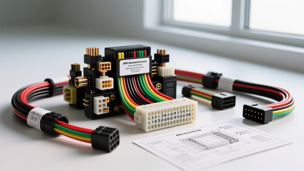
2006 Grand Prix Radio Wiring Diagram & System Architecture
The 2006 Pontiac Grand Prix, representing the eighth generation of GM's W-Body platform, utilizes a highly integrated multiplexed electrical system. Unlike older vehicles that relied on simple switched 12V ignition feeds, the 2006 Grand Prix audio system is governed by the Body Control Module (BCM) and relies heavily on the Class 2 Serial Data Bus for operational commands. When replacing the factory Delco head unit or diagnosing audio faults, understanding the interaction between the 24-pin main harness, the Retained Accessory Power (RAP) circuit, and the serial data network is critical.
This technical specification reference provides the exact pinout configurations, wire color codes, and AWG routing standards required for aftermarket stereo integration, amplifier bypasses, and OEM electrical troubleshooting. Because the factory radio acts as a node on the Class 2 data network, improper wiring or bypassing without the correct data retention module can trigger GM's THEFTLOCK security protocol, permanently disabling the head unit.
Main 24-Pin Harness Pinout Configuration
The primary connection point for the 2006 Grand Prix head unit is the GM 24-pin Delco connector (often split into two physical housings that mate together, designated as Connector C1 and C2). Below is the definitive pinout chart for the base and standard premium audio configurations. Note that pin assignments for amplified (Bose/Monsoon) systems differ slightly at the amplifier integration module rather than the head unit itself.
| Pin | Function | Wire Color | AWG / Notes |
|---|---|---|---|
| 1 | Left Front Speaker (+) | Tan | 18 AWG |
| 2 | Left Front Speaker (-) | Gray | 18 AWG |
| 3 | Right Front Speaker (+) | Light Green | 18 AWG |
| 4 | Right Front Speaker (-) | Dark Green | 18 AWG |
| 5 | Left Rear Speaker (+) | Brown | 18 AWG |
| 6 | Left Rear Speaker (-) | Yellow | 18 AWG |
| 7 | Right Rear Speaker (+) | Dark Blue | 18 AWG |
| 8 | Right Rear Speaker (-) | Light Blue | 18 AWG |
| 9 | Not Used / Reserved | - | - |
| 10 | Chassis Ground | Black/White | 14 AWG |
| 11 | Chassis Ground | Black/White | 14 AWG |
| 12 | Battery 12V+ (Constant) | Orange | 12 AWG |
| 13 | Accessory 12V+ (RAP Feed) | Yellow | 14 AWG |
| 14 | Panel Illumination | Gray | 20 AWG |
| 15 | Not Used | - | - |
| 16 | Class 2 Serial Data | Dark Green | 20 AWG (Shielded) |
| 17 | Steering Wheel Controls (SWC) | Purple/White | 22 AWG (Resistor Ladder) |
| 18 | OnStar Audio Mute / Data | Purple | 20 AWG |
Speaker Wire Color Codes & AWG Routing
The 2006 Grand Prix routes speaker-level signals directly from the head unit to the door modules in base audio configurations. GM utilizes a standardized color palette across its W-Body and H-Body platforms of this era. When tapping into these wires for an aftermarket line output converter (LOC) or a 4-channel amplifier, ensure you are using high-quality T-taps or, preferably, soldering and heat-shrinking the connections to prevent signal degradation and galvanic corrosion.
| Speaker Location | Positive (+) Wire | Negative (-) Wire | Impedance |
|---|---|---|---|
| Left Front (Door) | Tan | Gray | 4 Ohms |
| Right Front (Door) | Light Green | Dark Green | 4 Ohms |
| Left Rear (Deck/Door) | Brown | Yellow | 4 Ohms |
| Right Rear (Deck/Door) | Dark Blue | Light Blue | 4 Ohms |
According to the Haynes Pontiac Grand Prix repair manual, the speaker wires running through the door jambs are encased in a rubber accordion boot. Over time, the constant flexing of the door hinge can cause the 18 AWG copper strands to fatigue and break, resulting in intermittent audio dropouts. If you are troubleshooting a dead speaker, always perform a continuity test across the door jamb harness before condemning the head unit or the speaker voice coil.
Amplified vs. Base Audio Systems (Bose/Monsoon)
If your 2006 Grand Prix is equipped with the factory Monsoon or Bose amplified system, the head unit outputs low-level (preamp) signals rather than high-level speaker outputs. In these configurations, the wiring harness includes additional pins for amplifier turn-on and balanced audio shielding. The factory amplifier is typically located in the trunk or behind the rear seat bolster. Bypassing the factory amplifier requires running new 14 AWG or 12 AWG speaker wire from an aftermarket head unit directly to each door speaker, completely bypassing the factory amp and its degraded OEM wiring.
Retained Accessory Power (RAP) & Class 2 Data Integration
One of the most misunderstood aspects of the 2006 Grand Prix radio wiring diagram is the Retained Accessory Power (RAP) system. In older vehicles, the radio received a hard 12V+ signal from the ignition switch. In the 2006 W-Body, the radio receives constant 12V+ (Orange wire) and a RAP feed (Yellow wire). However, the radio will not power on until it receives a 'Wake-Up' command via the Class 2 Serial Data line (Dark Green, Pin 16).
The Class 2 data bus operates at 10.4 kbps using a single-wire, ground-referenced architecture governed by the SAE J1850 standard. When you insert the key and turn it to the ACC or RUN position, the BCM broadcasts a serial data message instructing the radio to power up. When you remove the key, the radio stays on until the driver's door is opened, at which point the BCM sends a 'Sleep' command.
Aftermarket Integration Warning: You cannot simply connect an aftermarket head unit's red accessory wire to the GM Yellow RAP wire and expect reliable operation. Because the factory radio manages data network termination, removing it without a proper interface module (such as the GMOS-LAN-09 or Axxess XSVI-2104-LAN) will cause the Class 2 bus to throw a U-code (Network Communication Fault), potentially disabling OnStar, steering wheel controls, and chime functions. Always use a data-bypass interface that translates the Class 2 serial commands into a standard 12V switched accessory output for your aftermarket stereo.
Steering Wheel Controls (SWC) & OnStar Retention
The 2006 Grand Prix utilizes a resistor-ladder network for its Steering Wheel Controls, located on Pin 17 (Purple/White). When a button is pressed, a specific resistance value is sent to the head unit. To retain these controls with an aftermarket radio, you must wire the Purple/White wire to an SWC interface module (like the Axxess ASWC-1) and configure the module via its LED diagnostic sequence.
OnStar integration is handled via the factory radio's internal amplifier and data routing. When OnStar is activated, the radio mutes the music and routes the cellular audio through the driver's front speaker. If you are removing the factory radio and wish to retain OnStar, you must use a specialized retention module (such as the Axxess GMOS-04) that intercepts the OnStar audio feed and mutes the aftermarket amplifier via a dedicated mute trigger wire.
Diagnostic Troubleshooting: Common W-Body Electrical Faults
When diagnosing audio system failures in the 2006 Grand Prix, use the following symptom-cause-fix decision tree to isolate the fault efficiently. For comprehensive vehicle-specific fitment data and harness adapter recommendations, the Crutchfield Vehicle Fit Database remains an excellent cross-reference tool for confirming harness compatibility.
- Symptom: Radio displays 'LOCKED' or 'THEFTLOCK' and will not power on.
Cause: The radio has lost its Class 2 data handshake with the BCM, or the battery was disconnected while the BCM was awake, triggering the anti-theft protocol.
Fix: Reconnect the battery, turn the ignition to RUN, and leave the radio powered on for 60 minutes. The BCM and radio will automatically re-sync the VIN data over the Class 2 bus and unlock. Do not disconnect power during this cycle. - Symptom: Alternator whine or ground loop noise through the speakers.
Cause: Improper grounding of the aftermarket head unit or amplifier. The W-Body chassis has known paint-over issues on the factory ground studs near the kick panels.
Fix: Scrape away paint and primer down to bare metal at the ground point. Use a 12 AWG ground wire with a crimped and soldered ring terminal, secured with a star washer and torque to 8 Nm (71 lb-in). - Symptom: Radio turns off immediately when the key is removed (No RAP function).
Cause: The aftermarket radio's red accessory wire was wired to a hard 12V ignition source instead of utilizing the RAP data interface, or the door jamb switch (which signals the BCM to kill RAP) is faulty.
Fix: Verify the door courtesy lights illuminate when the door is opened. If they do not, replace the door jamb plunger switch. If they do, re-wire the head unit accessory feed through a proper GM RAP data interface module. - Symptom: Intermittent audio loss from the driver's side speakers.
Cause: Fatigued 18 AWG speaker wires inside the driver's door rubber accordion boot.
Fix: Peel back the rubber boot, inspect the Tan and Gray wires for copper fatigue or broken shielding. Splice in a new section of 18 AWG OFC (Oxygen-Free Copper) wire using adhesive-lined heat shrink.
Final Installation Torque & Safety Specifications
When reinstalling the dashboard bezel and head unit cage, ensure all 7mm retaining bolts for the radio brackets are torqued to 2 Nm (18 lb-in) to prevent rattling against the HVAC plenum. Always disconnect the negative battery terminal (10mm nut) and wait 5 minutes for the BCM capacitors to discharge before splicing into the Class 2 data line or the constant 12V Orange feed to prevent shorting the BCM's internal data driver IC.