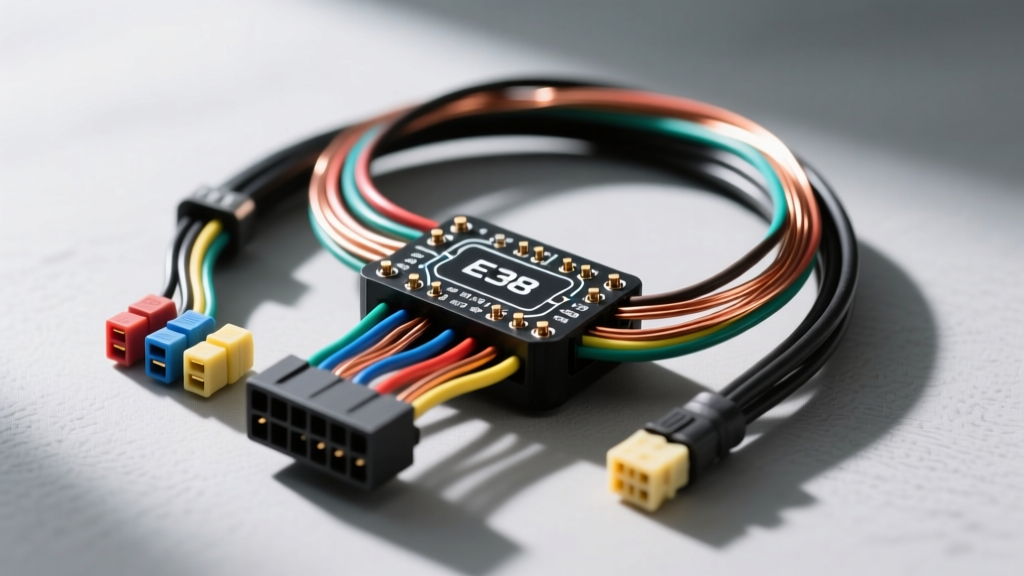
The Anatomy of a Stand Alone Wiring Harness for LS Swap
Swapping a Gen III or Gen IV GM V8 into a classic muscle car, off-road rig, or non-GM chassis is one of the most popular automotive modification projects today. However, the factory engine control module (ECM) relies on a complex network of body control modules (BCM), instrument clusters, and CAN-bus networks. To run the engine independently, you must fabricate or modify a stand alone wiring harness for LS swap applications. This guide details the electrical architecture, wire gauge requirements, and pinout strategies for building a reliable, noise-free harness centered around the GM E38 and E67 ECM platforms.
Donor Harness Teardown & Bulkhead Elimination
When starting with a salvage yard harness (such as one pulled from a 2008-2013 Corvette or Camaro SS), the first step is eliminating the C100 and C305 bulkhead connectors. These multi-pin firewall connectors bridge the engine bay to the interior BCM and instrument panel. For a true stand alone wiring harness for LS swap builds, you will physically cut the harness at the firewall, retaining only the engine-side pigtails. You must then trace and consolidate the three primary power feeds (Battery+, Ignition+, and Crank Signal) and the four primary ground circuits directly to a centralized, weather-sealed fuse and relay block mounted in the engine bay.
Wire Gauge Selection & SAE Insulation Standards
Never use standard PVC-jacketed wire under the hood. According to SAE J1128 standards, engine compartment wiring must utilize cross-linked polyethylene (XLPE) insulation, commonly known in the industry as TXL or GXL wire. TXL wire withstands continuous temperatures up to 125°C (257°F) and resists abrasion from engine vibration, heat cycling, and automotive fluids. When extending donor harness wires to reach your custom fuse block, always use crimp-and-solder butt connectors or ultrasonic welding, sealed with dual-wall heat shrink containing an adhesive inner lining to prevent capillary moisture wicking.
| Circuit Function | AWG Size | Typical OEM Color | Connector / Terminal Type |
|---|---|---|---|
| ECM Main Power (BAT+) | 10 AWG | Red | Metri-Pack 630 / Ring Terminal |
| Injector Feed (Switched 12V) | 14 AWG | Pink | Delphi GT 280 |
| 5V Reference (TPS/MAP/APP) | 18 AWG | Gray | Metri-Pack 150 |
| Low Current Sensor Ground | 18 AWG | Black/White | Metri-Pack 150 |
| Alternator Sense (F-Terminal) | 18 AWG | Brown | Packard 56 Series |
| Cooling Fan Relay Control | 16 AWG | Dark Green | Delphi GT 280 |
Sensor Signal Integrity & EMI Mitigation
The most common cause of a failed LS swap is electromagnetic interference (EMI) corrupting the crankshaft position sensor (CKP) or camshaft position sensor (CMP) signals. The GM E38 ECM relies on a 58-tooth reluctor wheel for the CKP. The signal is a low-voltage AC waveform that is highly susceptible to noise from aftermarket ignition systems, alternator ripple, and high-amperage cooling fan motors.
Crankshaft and Camshaft Position Sensor Routing
When building your stand alone wiring harness for LS swap projects, never route CKP or CMP wires parallel to injector feeds, coil power wires, or high-voltage spark plug wires. Maintain a minimum 2-inch separation between 5V reference/sensor signal wires and 12V+ high-current inductive circuits. If you must extend the CKP sensor wires due to custom engine mounting, use Shielded Twisted Pair (STP) cable. Crucially, the shield drain wire must be grounded exclusively at the ECM sensor ground pin (typically Pin 18 or 19 on the Black X1 connector), never at the engine block, to avoid creating a ground loop that will induce fatal noise into the timing data.
Alternator & Charging System Integration
Modern GM alternators (such as the AD244 or CS130D) require specific excitation signals to begin charging. A common mistake in LS swaps is wiring the alternator as a generic "one-wire" setup, which leaves the battery undercharged at idle and causes the ECM to throw a P0562 (System Voltage Low) code. The factory 4-pin connector includes an L (Lamp) terminal and an F (Field/Sense) terminal.
Excitation Signals and P0562 Prevention
You must wire the L terminal to a switched 12V ignition source through a 100-ohm resistor or an LED indicator bulb to wake up the internal voltage regulator. The F terminal must be routed directly to the main battery positive post (or the main fuse block battery feed) to accurately sense system voltage. Referencing the GM Upfitter Body Builder Guides, failing to provide the proper excitation signal will result in the alternator defaulting to a 13.2V limp-home mode, which is entirely insufficient for high-draw electric cooling fans, in-tank fuel pumps, and electric water pumps.
Fuel Pump Flow Control Module (FPCM) Bypass Strategies
The GM E38 ECM does not drive the fuel pump directly; it communicates via CAN-bus to a Fuel Pump Flow Control Module (FPCM) to pulse-width modulate the fuel pump speed based on demanded fuel pressure. In a stand alone wiring harness for LS swap applications, retaining the OEM FPCM adds unnecessary weight, wiring complexity, and failure points. The professional workaround is to flash the ECM (using HP Tuners or EFI Live) to disable the FPCM requirement. You then run a standard 3-bar or 4-bar return-style fuel system with a mechanical bypass regulator, and wire a traditional 12V relay for the fuel pump. If you must retain the returnless PWM system for emissions or packaging reasons, you must include the FPCM in your harness build, routing the CAN High (Pin 5) and CAN Low (Pin 6) twisted pair from the ECM to the FPCM, ensuring the 120-ohm termination resistors remain intact on the network.
Grounding Topology: The Star Ground Requirement
A stand alone wiring harness for LS swap reliability hinges entirely on the grounding strategy. The GM service manuals dictate a "Star Ground" topology for powertrain components. You must establish a heavy-gauge (1/0 AWG or 2/0 AWG) ground strap directly from the alternator mounting bolt or cylinder head to the vehicle chassis, and another from the engine block to the starter motor ground.
More importantly, the ECM's low-current sensor grounds (Pins 2, 3, and 4 on the Gray X2 connector) must be bolted directly to a clean, unpainted surface on the aluminum cylinder head using a dedicated M6 or M8 stainless steel bolt. Do not ground the ECM to the intake manifold, as composite manifolds and rubber gaskets isolate the electrical path. Furthermore, do not ground the ECM sensor pins to the chassis, as voltage drops across the engine mounts during heavy acceleration will introduce catastrophic noise into the 5V reference circuits, causing erratic TPS and MAF readings.
Cooling Fan Relay Integration & Flyback Diodes
The E38 ECM features dedicated outputs for dual cooling fan relays. Pin 32 on the Black X1 connector controls Fan 1 (Low Speed), and Pin 33 controls Fan 2 (High Speed). Because the ECM drivers are low-side switches designed to trigger relay coils (drawing roughly 150mA), you must use external 30A/40A ISO mini-relays to handle the 20A+ inrush current of the electric fans. Wire the relay coil's positive terminal to a fused ignition source, and the negative terminal to the ECM pin. It is highly recommended to place a flyback diode (1N4001) across the relay coil terminals to suppress the inductive voltage spike when the ECM de-energizes the relay. This simple addition protects the delicate internal ECM driver transistors from frying, a common issue documented in Delphi Powertrain Connection Systems technical bulletins regarding high-inductance loads.
Conclusion
Fabricating a stand alone wiring harness for LS swap projects requires meticulous attention to wire selection, signal shielding, and grounding topology. By adhering to OEM-style routing, utilizing high-temperature TXL wire, and properly managing the CAN-bus and PWM fuel system requirements, you ensure that your Gen III or Gen IV V8 operates flawlessly. Proper planning of the E38 pinouts and bulkhead elimination will save you hours of diagnostic troubleshooting, resulting in a clean, reliable engine bay that performs exactly as the engineers intended.