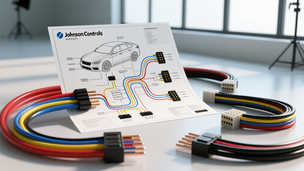
Project Overview: Integrating Digital Climate Control in Restomods
Upgrading a classic vehicle from a cable-operated heater valve and resistor-based blower motor to a modern, solid-state digital climate control system is one of the most impactful comfort modifications you can perform. For many advanced restomod and EV-swap projects, fabricators utilize OEM-style digital HVAC control heads originally manufactured by Johnson Controls (JCI). These modules, often salvaged from late-90s and early-2000s premium platforms or sourced as new-old-stock (NOS) universal units, offer precise temperature mapping, automatic blend door actuation, and pulse-width modulation (PWM) blower control.
However, integrating a Johnson Controls digital HVAC module into a custom chassis requires a thorough understanding of its specific logic circuits, sensor inputs, and actuator feedback loops. Unlike standard aftermarket universal kits, JCI modules rely on precise voltage divider networks for thermistors and specific PWM frequencies to prevent blower motor whine. This guide provides the definitive Johnson Controls wiring diagram, pinout configurations, and technical specifications required to execute a flawless climate control upgrade.
Wire Selection and SAE J1128 Compliance
Before splicing into your vehicle's main harness, you must select the correct primary wire. For automotive HVAC control circuits, we strictly adhere to SAE J1128 standards for low-tension primary cable. We recommend using Cross-Linked Polyethylene (TXL) wire rather than standard PVC, as TXL offers superior heat resistance (up to 125°C) and a thinner insulation wall, allowing for tighter bundle routing behind the dashboard.
| Circuit Type | AWG Size | Insulation | Max Current | Color Code Standard |
|---|---|---|---|---|
| Main Power / Ground | 14 AWG | TXL | 15A | Red (Power) / Black (Ground) |
| Ignition / Memory | 16 AWG | TXL | 10A | Pink (Ign) / Yellow (Mem) |
| Actuator Motors | 18 AWG | TXL | 6A | Brown / Orange |
| Sensor Signals | 20 AWG Shielded | TXL/Shield | 1A | Light Blue / White |
Johnson Controls Wiring Diagram & 16-Pin Connector Pinout
The most common Johnson Controls digital HVAC head utilized in custom swaps features a 16-pin Delphi Weather-Pack or TE Connectivity AMP Superseal connector. Below is the comprehensive pinout reference. When building your custom harness, ensure that all sensor signal wires are routed away from high-current ignition or alternator output wires to prevent electromagnetic interference (EMI).
Primary 16-Pin Configuration Table
| Pin | Function | Wire Color | AWG | Destination / Notes |
|---|---|---|---|---|
| 1 | Ignition 12V+ | Pink | 16 | Fuse box (Run/Start circuit) |
| 2 | Constant 12V+ (Memory) | Yellow | 16 | Battery via 5A inline fuse |
| 3 | Chassis Ground | Black | 14 | Clean metal chassis point (Ring terminal) |
| 4 | Blower PWM Signal | Purple | 18 | PWM Blower Motor Controller Module |
| 5 | A/C Compressor Clutch | Dark Green | 18 | Trigger side of A/C compressor relay |
| 6 | Cabin Temp Sensor Signal | Light Blue | 20 | NTC Thermistor (Shielded wire required) |
| 7 | Cabin Temp Sensor Ground | White | 20 | NTC Thermistor return (Do not share ground) |
| 8 | Blend Door Actuator Motor + | Brown | 18 | Blend door DC motor positive terminal |
| 9 | Blend Door Actuator Motor - | Orange | 18 | Blend door DC motor negative terminal |
| 10 | Actuator Feedback Pot | Gray | 20 | Wiper pin of 5-wire actuator potentiometer |
| 11 | Panel Illumination | Light Green | 18 | Headlight switch dimmer circuit (PWM or analog) |
| 12 | Defrost Relay Trigger | Dark Blue | 18 | Trigger for HVAC mode/defrost relay |
| 13 | Recirculation Motor + | Tan | 18 | Fresh air/recirc door actuator |
| 14 | Recirculation Motor - | Light Brown | 18 | Fresh air/recirc door actuator |
| 15 | High-Pressure Cutout | Red/White | 18 | Input from A/C binary/trinary safety switch |
| 16 | Evaporator Temp Sensor | Violet | 20 | Evap core thermistor (prevents coil freezing) |
Diagram Routing Notes: Power and Ground Isolation
A critical failure mode in restomod HVAC swaps is "ghost switching," where the digital display resets or the blend door hunts for position upon engine cranking. This is caused by voltage drops on shared ground circuits. Pin 3 (Chassis Ground) must be routed directly to a dedicated, sanded bare-metal grounding stud on the firewall or chassis crossmember. Do not daisy-chain this ground with radio amplifiers or ECU logic grounds. Use a minimum 14 AWG wire and secure it with a stainless steel ring terminal, torqued to 10-15 Nm depending on the stud size.
Sensor Integration: Thermistors and Voltage Dividers
The Johnson Controls module calculates cabin temperature using a Negative Temperature Coefficient (NTC) thermistor connected between Pin 6 and Pin 7. Most JCI modules are calibrated for a 10kΩ NTC thermistor at 25°C (77°F) with a Beta (B) value of approximately 3435.
Because the module reads temperature by measuring the voltage drop across a precision internal voltage divider, any resistance added by poor wire connections or undersized wire will skew the temperature reading. This is why we mandate 20 AWG shielded cable for Pins 6 and 7. The shield drain wire must be grounded only at the HVAC control head end (Pin 3 ground), leaving the sensor end floating to prevent ground loops. If your cabin reads 5-10 degrees warmer than actual, check for parasitic resistance in your crimp connections at the thermistor pigtail.
Blend Door Actuator Calibration and Stall Current
Digital climate control relies on closed-loop feedback to position the blend door. The Johnson Controls module drives the DC motor on Pins 8 and 9 while simultaneously reading the position feedback from the internal potentiometer on Pin 10.
Crucial Modification Insight: Many universal aftermarket actuators draw up to 3-4 amps under stall load (when the door reaches its mechanical hard stop). If you use standard 20 or 22 AWG wire for the motor circuit, the voltage drop will cause the JCI module to falsely detect a "door jammed" fault code, aborting the calibration sequence. Always use 18 AWG TXL wire for actuator motor feeds, and ensure your crimp terminals (such as TE Connectivity Superseal terminals) are compressed with a proper ratcheting crimper to ensure zero millivolt drop across the joint.
PWM Blower Motor Upgrades
Classic vehicles use resistor packs to control blower speed, which wastes massive amounts of energy as heat and offers limited granularity. The Johnson Controls module outputs a 5V PWM logic signal on Pin 4. This signal must be fed into a dedicated high-current automotive PWM blower controller (capable of handling 20A+ continuous), which then drives the blower motor ground.
Ensure your chosen PWM controller operates at a frequency above 20 kHz. Frequencies below 1 kHz will result in an audible, high-pitched whine from the blower motor armature that resonates through the dashboard ducting.
Troubleshooting Decision Tree
When your custom HVAC integration fails to operate as expected, use this systematic diagnostic tree to isolate the fault:
- Symptom: Display powers on, but blower motor remains dead at all speeds.
- Check 1: Measure Pin 4 with an oscilloscope or multimeter (duty cycle mode). Does the duty cycle change when adjusting fan speed? If NO, the module logic board is faulty.
- Check 2: If YES, verify 12V+ at the PWM controller's main power feed and check the ground path to the blower motor.
- Symptom: Cabin temperature reads 120°F (49°C) constantly; A/C clutch never engages.
- Check 1: The module is seeing an open circuit on the thermistor. Inspect the shielded wiring on Pins 6 and 7 for a broken core or severed shield short.
- Check 2: Measure the thermistor resistance directly at the sensor. It should read ~10kΩ at room temperature. If it reads infinite, replace the thermistor.
- Symptom: Blend door clicks repeatedly and never achieves target temperature.
- Check 1: Actuator feedback mismatch. The module is driving the motor but the potentiometer signal on Pin 10 is not changing. Verify the 5-wire actuator is properly ganged to the blend door shaft.
- Check 2: Check for voltage drop on Pins 8 and 9 during actuation. If voltage at the actuator drops below 9V, upgrade the wire to 16 AWG.
Expert Tips for Clean Restomod Integrations
To maintain a factory-level aesthetic and ensure long-term reliability in a high-vibration environment, avoid using generic butt-splices and electrical tape. Invest in a Deutsch DT or Delphi Weather-Pack crimping system (referencing Haynes Automotive Electrical Basics for proper terminal insertion techniques). Apply dielectric grease (such as Nyogel 760G) to all sensor and connector interfaces to prevent galvanic corrosion, especially if the vehicle will be exposed to marine environments or harsh winter road salts. By strictly following this Johnson Controls wiring diagram and respecting the specific signal requirements of digital climate control modules, your restomod will deliver modern, set-it-and-forget-it comfort.