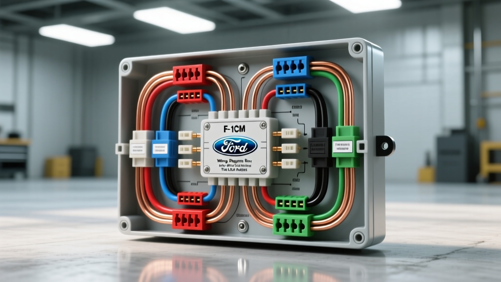
Introduction to Smart Junction Box Diagnostics
Modern vehicles have largely replaced traditional passive fuse blocks with Smart Junction Boxes (SJBs) and integrated Body Control Modules (BCMs). When diagnosing parasitic draws, CAN bus communication faults, or localized power failures, accessing the correct wiring diagram for junction box routing is only the first step. The true challenge lies in the physical execution of the diagnostic strategy without causing secondary damage to high-density connectors. This comprehensive cost and tool requirements analysis focuses on the 2015-2020 Ford F-150 Passenger Compartment Junction Box (integrated BCM), detailing the exact financial and technical investments required for professional-grade electrical troubleshooting.
Essential Tool Requirements & Cost Breakdown
Interpreting a wiring diagram for junction box layouts requires specialized test equipment. Standard test lights or low-impedance multimeters can easily destroy the internal logic boards of an SJB. Below is the required tooling matrix for proper diagnostics, including estimated capital expenditure for an independent shop or advanced DIYer.
| Tool Category | Specific Recommendation | Purpose | Est. Cost |
|---|---|---|---|
| Automotive DMM | Fluke 88V (High Impedance >10MΩ) | Back-probing CAN bus and logic circuits without loading the SJB. | $420.00 |
| Breakout Box | OEM-Specific 38-Pin/38-Pin Adapter | Reading live data while the junction box connector is fully mated. | $185.00 |
| Terminal Release Kit | Delphi/Aptiv GT150 & GT280 Depin Tools | Extracting damaged terminals without breaking the plastic retaining tangs. | $65.00 |
| Diagram Software | Mitchell 1 ProDemand / ALLDATA | Accessing OEM wiring schematics, pinout matrices, and connector end-views. | $45.00/mo |
| Thermal Camera | FLIR C5 or similar | Identifying high-resistance junction box bus bar connections under load. | $350.00 |
Total Initial Diagnostic Investment: ~$1,065.00 (excluding software subscriptions).
Interpreting the Wiring Diagram for Junction Box Connectors
The Ford F-150 BCM/Junction Box utilizes several high-density connectors, primarily C2280A (38-pin) and C2280B (38-pin). When referencing the wiring diagram for junction box C2280A, technicians must understand the matrix layout. The diagram will list the cavity number, circuit designation, wire color, and AWG size. Unlike older vehicles, modern diagrams also specify the terminal type (e.g., female GT150) and the mating connector ID.
Connector C2280A Pinout & Wire Specifications
Below is a critical reference table extracted from the OEM wiring diagram for junction box C2280A, highlighting the high-speed CAN bus and primary power feeds that are most frequently involved in diagnostic scenarios.
| Pin | Circuit Function | Wire Color | AWG / mm² | Terminal Type | Diagnostic Notes |
|---|---|---|---|---|---|
| 1 | MS-CAN High (+) | White/Blue (WH/BU) | 20 AWG (0.5mm²) | Female GT150 | Must read 60Ω to Pin 2 when network is powered down. |
| 2 | MS-CAN Low (-) | White/Brown (WH/BN) | 20 AWG (0.5mm²) | Female GT150 | Check for short-to-ground if MS-CAN modules drop offline. |
| 14 | Battery Feed (B+) | Yellow/Red (YE/RD) | 10 AWG (5.0mm²) | Female GT280 | Protected by 30A Mega Fuse. High heat failure point. |
| 22 | Primary Ground | Black/White (BK/WH) | 14 AWG (2.0mm²) | Ring Terminal | Routes to Ground Stud G200. Torque spec: 10 Nm. |
| 35 | Ignition Start/Run | Violet/Orange (VT/OG) | 18 AWG (0.8mm²) | Female GT150 | Should show 12.2V-12.6V during cranking. |
Cost Analysis: Diagnostics vs. Junction Box Replacement
When the wiring diagram for junction box troubleshooting points to an internal SJB failure (such as a blown internal trace or failed solid-state relay), replacement is required. The cost structure involves much more than just the part price; programming and labor dominate the invoice.
- Diagnostic Time: 1.5 hours @ $150/hr = $225.00 (Includes voltage drop testing and CAN bus oscilloscope verification).
- Labor (R&I Dash Trim & Junction Box): 3.2 hours @ $150/hr = $480.00. The F-150 passenger junction box is buried behind the lower instrument panel insulator and knee bolster.
- OEM Junction Box Assembly (Part # KL3Z-14A068-B): $415.00 - $550.00 depending on trim level options (towing package, upfitter switches).
- Module Programming (FDRS Token): $50.00 for a 72-hour Ford Diagnostic & Repair System (FDRS) license. Note: The BCM requires As-Built data configuration and a PATS (anti-theft) parameter reset, which requires an active internet connection to the Ford server.
- Total Estimated Repair Cost: $1,170.00 - $1,305.00.
Real-World Failure Modes & Diagnostic Decision Tree
Before condemning the junction box based on the wiring diagram, technicians must rule out external physical failures. Use this decision tree when the schematic indicates a loss of power or communication:
- Symptom: Intermittent MS-CAN Bus Faults (U-Codes in multiple modules).
- Check 1: Inspect C2280A Pins 1 & 2 for terminal fretting corrosion. The GT150 terminals are prone to micro-movement oxidation. Fix: Apply Dielectric Grease (Motorcraft XL-1) and ensure terminal retention tangs are engaged.
- Check 2: Verify 60Ω resistance across Pins 1 and 2 with the battery disconnected. If reading 120Ω, an internal SJB termination resistor has failed, requiring SJB replacement.
- Symptom: Melted Connector at Pin 14 (B+ Feed).
- Check 1: Perform a voltage drop test across the 10 AWG Yellow/Red wire from the battery junction box to C2280A Pin 14 under a 20A simulated load. A drop >0.2V indicates high resistance.
- Check 2: Inspect the female GT280 terminal for spread pins. Fix: Use a terminal resizing tool or pigtail a new OEM connector (WPT-1246) using a crimp-and-seal heat shrink butt connector. Do not solder 10 AWG power feeds in high-vibration areas, as solder wicking creates a brittle stress point.
- Symptom: Parasitic Draw Originating at Junction Box.
- Check 1: Use a thermal camera on the SJB casing after the vehicle enters sleep mode (approx. 45 minutes post-ignition off). A hot spot indicates an internal solid-state switch is stuck closed.
- Check 2: Review the wiring diagram for junction box outputs. Pull the specific micro-fuse associated with the hot circuit. If the draw drops, the fault is downstream. If the draw persists, the SJB internal logic board is shorted.
Authoritative References & Standards
Accurate diagnostics require adherence to industry standards and OEM protocols. The data and procedures referenced in this analysis are derived from the following authoritative automotive electrical resources:
- SAE J1939 Standard - Society of Automotive Engineers guidelines for CAN bus network topology, termination resistance (60Ω), and voltage thresholds.
- Fluke Automotive Diagnostics - Technical documentation on high-impedance testing and preventing module damage during back-probing of smart junction boxes.
- Ford Diagnostic & Repair System (FDRS) - Official OEM portal for module programming, As-Built data retrieval, and BCM configuration protocols.
Mastering the wiring diagram for junction box systems requires a blend of theoretical schematic knowledge and practical, tool-driven execution. By investing in the correct high-impedance test equipment and understanding the precise AWG and terminal specifications of the BCM connectors, technicians can accurately diagnose complex electrical faults while minimizing the risk of costly secondary damage to the vehicle's central nervous system.