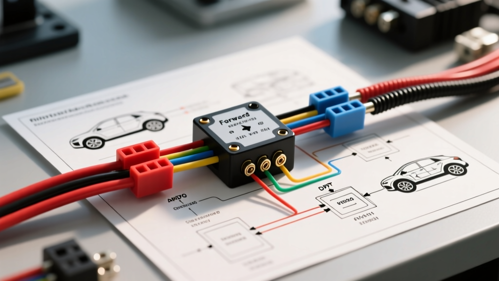
Understanding Modern Forward/Reverse (F/R) Switch Logic
When working with electric vehicles, Low-Speed Vehicles (LSVs), and electric UTVs like the Polaris Ranger EV, the forward/reverse (F/R) switch is a critical drivetrain component. Historically, older Series DC golf carts utilized massive 600A-rated knife switches or heavy contactors to physically reverse the armature or field polarity. However, modern EV conversions and AC drivetrain systems utilize solid-state motor controllers (such as the Curtis 1238 or Sevcon Gen4). In these systems, the F/R switch does not carry high traction current. Instead, it acts as a low-current logic input that signals the controller's IGBT bridge to alter the phase sequence.
This guide provides a comprehensive, practical installation and wiring diagram for a 6-terminal DPDT (Double Pole, Double Throw) logic-level F/R switch with a center-off neutral position. This setup ensures safe, reliable directional control while integrating vital safety interlocks to prevent catastrophic inverter faults.
Required Components and Wire Specifications
To ensure reliability in harsh automotive and off-road environments, all wiring must adhere to SAE J1128 standards for low-tension primary cable. We recommend using TXL (Thin-wall cross-linked) wire for its superior resistance to heat, chemicals, and abrasion.
- Switch: IP67-rated 6-Terminal DPDT Toggle/Rocker Switch (Center-Off), rated for 12V/24V DC logic (e.g., Cole-Hersee 55055 series or equivalent marine-grade switch).
- Connectors: Deutsch DT Series (DT06-6S plug and DT04-6P receptacle) with integrated wedgelocks to prevent vibration-induced back-out.
- Wire (Logic): 18 AWG TXL (Ampacity ~16A, more than sufficient for <1A logic signals).
- Wire (B+ Feed): 14 AWG TXL for the main switched power input.
- Terminals: Deutsch solid copper crimp contacts, sized for 18-20 AWG wire cavities.
6-Terminal DPDT Switch Pinout and Wiring Diagram
The following table details the exact pinout configuration for the 6-way Deutsch connector mating to the F/R switch. This configuration separates the directional logic from the safety interlock circuit, a requirement for modern motor controllers to prevent High Pedal Disable (HPD) faults.
| Pin | Function | Wire Color | AWG Size | Destination / Notes |
|---|---|---|---|---|
| 1 | B+ Logic Input | Red | 14 AWG | Fused 12V/48V ignition source (Max 5A fuse) |
| 2 | Forward Logic Out | Blue | 18 AWG | Controller Forward Input Pin |
| 3 | Reverse Logic Out | Yellow | 18 AWG | Controller Reverse Input Pin |
| 4 | Brake Interlock In | Green | 18 AWG | Output from Brake Pedal Microswitch |
| 5 | Neutral / Center-Off | White | 18 AWG | Controller Neutral / Park Input Pin |
| 6 | Logic Ground | Black | 18 AWG | Vehicle Chassis Ground / Controller Logic GND |
Step-by-Step Installation Guide
Follow these steps to assemble and install the F/R logic harness. Adherence to IPC/WHMA-A-620 harness assembly standards is highly recommended for crimping and routing.
- Lockout/Tagout (LOTO): Disconnect the main traction battery pack and isolate the high-voltage contactors. Wait 5 minutes for the motor controller's internal capacitors to discharge before working near the logic harness.
- Prepare the Wiring: Cut six lengths of TXL wire to the required distance between the dashboard switch panel and the motor controller logic header. Strip 5mm (0.20 inches) of insulation from each end.
- Crimp the Contacts: Using a calibrated Deutsch DT crimp tool, crimp the 18-20 AWG contacts to the wires. Perform a pull-test on one sacrificial crimp to verify the tool is applying the correct deformation (typically 15-20 lbs of pull-force retention).
- Insert into Connector Housing: Push the crimped pins into the DT06-6S plug housing until you hear a distinct 'click'. Insert the orange wedgelock to secure the pins in place.
- Mount the Switch: Install the DPDT switch in the dashboard. If the switch is exposed to the elements (e.g., in an open-cab UTV), apply dielectric grease to the switch terminals before mating the connector to prevent moisture ingress and galvanic corrosion.
- Route the Harness: Route the logic harness at least 6 inches away from high-current phase cables (the thick 4/0 AWG motor leads) to prevent Electromagnetic Interference (EMI) from inducing phantom voltage in the logic wires, which can cause erratic controller behavior.
Integrating the Brake Interlock (Crucial Safety Step)
The most common and dangerous mistake in EV F/R wiring is omitting the brake interlock. If a driver shifts from Forward to Reverse while the throttle is depressed, the motor controller will attempt to instantly reverse the phase sequence. This causes massive current spikes that can weld the main contactors, destroy the IGBTs, or trigger a severe HPD (High Pedal Disable) fault, locking the vehicle in neutral until the system is rebooted.
How to wire the interlock: The Green wire (Pin 4) must be routed through a normally-open (NO) microswitch mounted on the brake pedal assembly. The B+ source feeds the brake switch; when the pedal is pressed, power flows through Pin 4, internally bridging to the directional logic pins (Pins 2 and 3) inside the DPDT switch. This ensures the directional signal can only reach the motor controller if the brake is actively applied, guaranteeing the throttle is at 0%.
Troubleshooting Common F/R Switch Failures
When directional issues arise, use a digital multimeter (DMM) to diagnose the logic circuit. Refer to the Curtis Instruments Controller Manuals for specific logic input voltage thresholds.
| Symptom | Probable Cause | Diagnostic Fix / Action |
|---|---|---|
| Vehicle moves forward, but no reverse. | Open circuit on Reverse Logic wire (Pin 3) or failed internal switch contact. | Backprobe Pin 3 with DMM. If 0V when shifted to Reverse, replace switch. If 12V is present at switch but not at controller, repair broken Yellow wire. |
| Controller throws HPD fault upon shifting. | Brake interlock bypassed or miswired; driver shifting while throttle is engaged. | Verify Green wire (Pin 4) only receives B+ when the brake pedal is physically depressed. Adjust brake microswitch plunger depth. |
| Intermittent Neutral fault or sudden loss of drive. | Vibration causing Deutsch pin back-out or failing center-off detent. | Inspect the wedgelock on the DT connector. Check continuity on the White wire (Pin 5) while wiggling the harness to find chafing or broken strands. |
| Vehicle creeps forward in Neutral. | Leakage voltage on Forward logic line due to EMI or moisture in the switch housing. | Check for phantom voltage on the Blue wire in Neutral. Apply dielectric grease and ensure logic ground (Pin 6) has less than 0.1 ohm resistance to chassis. |
By treating the F/R switch as a precision logic input rather than a simple high-current toggle, you ensure the longevity of your motor controller and the safety of the vehicle's drivetrain. Always verify your specific controller's programming parameters to ensure the logic inputs are configured for 'Active High' (switched B+) rather than 'Active Low' (switched ground) before applying power.