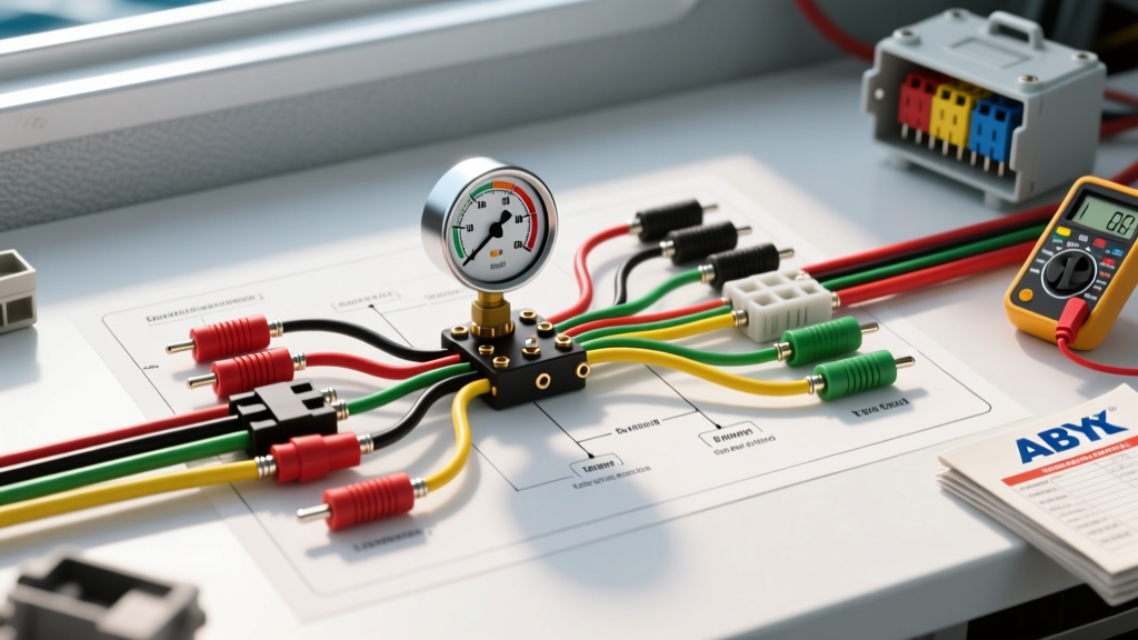
Introduction to Marine Fuel Gauge Wiring
When consulting a boat fuel gauge wire diagram, marine electricians and DIY boaters must recognize that marine environments demand drastically stricter safety protocols than automotive applications. A boat's electrical system is subjected to constant vibration, high humidity, saltwater corrosion, and, most critically, explosive fuel vapors in the bilge. Misinterpreting a wiring schematic or ignoring marine-specific standards doesn't just result in an inaccurate fuel reading; it can lead to electrical fires or catastrophic explosions. This guide breaks down the anatomy of marine fuel gauge circuits, highlights critical safety warnings mandated by the American Boat and Yacht Council (ABYC), and details the most common wiring mistakes made during installation and troubleshooting.
The Anatomy of a Boat Fuel Gauge Wire Diagram
A standard marine fuel gauge operates on a simple variable resistance circuit. Unlike digital CAN-bus systems found in modern cars, traditional analog marine gauges utilize a 4-post or 5-post terminal configuration on the back of the helm display. Understanding these terminals is the first step in reading any boat fuel gauge wire diagram accurately:
- I (Ignition): Receives switched 12V DC power from the ignition switch or accessory breaker. Standard ABYC wire color: Purple (or Violet).
- G (Ground): Connects to the vessel's DC negative ground bus. Standard ABYC wire color: Black.
- S (Sender): Carries the variable resistance signal from the fuel tank sender unit. Standard ABYC wire color: Pink.
- L (Illumination): Powers the gauge's internal backlighting, usually tied to the navigation light circuit. Standard ABYC wire color: Blue.
All wiring should be 16 AWG or 18 AWG marine-grade, tinned, stranded copper wire (UL 1426 certified) to resist the capillary action of moisture and the corrosive effects of salt air.
Critical Safety Warnings for Marine Electrical Work
1. Ignition Protection in the Bilge
The most severe safety hazard when wiring a fuel sender is the risk of igniting trapped gasoline vapors. Under USCG 33 CFR 183.410 Ignition Protection standards, any electrical component installed in the engine compartment or bilge space of a gasoline-powered vessel must be ignition protected. This means the fuel sender unit must be enclosed or designed so that any internal spark cannot ignite a surrounding hydrocarbon-air mixture. Never substitute an automotive fuel sender for a marine-rated, ignition-protected sender.
2. Overcurrent Protection and the 7-Inch Rule
According to the ABYC E-11 AC & DC Electrical Systems standard, overcurrent protection (fuses or circuit breakers) must be installed as close to the power source as possible. If the wire from the battery or main bus to the ignition switch is not already protected, the branch circuit feeding the fuel gauge's 'I' terminal must be fused within 7 inches of the power tap. A short in the purple ignition wire without a fuse can melt the wiring harness and ignite the fiberglass helm.
5 Common Mistakes When Reading a Boat Fuel Gauge Wire Diagram
Mistake 1: Mismatched Sender and Gauge Resistance
The most frequent reason a newly installed marine fuel gauge reads backward, sticks on 'Full', or pegs 'Empty' is a mismatch in ohm ratings. Automotive gauges typically use a 73-10 ohm or 240-33 ohm sweep, but marine standards vary wildly by manufacturer and region. If your boat fuel gauge wire diagram specifies a 33-240 ohm gauge (Standard US Marine), but you install a 10-180 ohm VDO sender, your fuel readings will be dangerously inaccurate. Always verify the ohm sweep on both the gauge casing and the sender flange before pulling the pink wire through the rigging chase.
Mistake 2: Relying on the Fuel Tank for Grounding
In automotive applications, the fuel sender often grounds through its metal mounting flange directly to the steel chassis. On a boat, relying on the tank for a ground is a critical error. Many modern marine fuel tanks are constructed from cross-linked polyethylene (plastic), which provides zero ground path. Even on aluminum tanks, corrosion between the sender flange and the tank, or between the tank and the hull ground strap, will create a high-resistance ground loop. This results in erratic gauge behavior. The Fix: Always run a dedicated 16 AWG black ground wire directly from the sender's dedicated 'G' terminal (or the sender body grounding screw) back to the helm's negative bus bar.
Mistake 3: Using Untinned Automotive Wire
Using standard automotive primary wire (SAE J1128) instead of marine wire (UL 1426) is a ticking time bomb. Untinned copper wire exposed to marine humidity will quickly oxidize, turning black and brittle. This 'black death' increases electrical resistance, which alters the ohm reading on the pink sender wire, causing the fuel gauge to read lower than the actual fuel level. Always use tinned copper wire and seal all crimps with adhesive-lined marine heat shrink.
Mistake 4: Daisy-Chaining Gauge Power and Illumination
Boaters often attempt to save wire by daisy-chaining the purple 'I' (Ignition) and blue 'L' (Illumination) wires from one gauge to the next. If a connection fails at the first gauge, the entire instrument cluster dies. Furthermore, tying the illumination circuit to the ignition circuit means your gauges will either never light up at night, or your gauge internals will be subjected to the higher voltage drop of the lighting circuit. Run individual homeruns to a fused terminal block or use a proper marine gauge wiring harness.
Mistake 5: Skipping the Dielectric Grease
The connection at the fuel sender's spade terminal in the bilge is highly susceptible to galvanic corrosion and moisture ingress. Failing to coat the spade connector and the terminal post with a marine-grade dielectric grease (or a corrosion inhibitor like Boeshield T-9) will result in a high-resistance joint within months, tricking the gauge into reading 'Empty'.
Marine Fuel Sender Resistance & Wire Color Specification Chart
| Standard / Brand | Resistance Sweep (Empty to Full) | Common Application | ABYC Sender Wire Color |
|---|---|---|---|
| US Marine Standard | 33 Ω to 240 Ω | Most domestic US builders (Sea Ray, Grady-White) | Pink |
| European / ISO | 0 Ω to 190 Ω | European imports, Volvo Penta OEM gauges | Pink |
| VDO / Faria | 10 Ω to 180 Ω | Aftermarket VDO gauges, older European vessels | Pink |
| Stewart-Warner | 240 Ω to 33 Ω | Specific SW aftermarket kits (Reverse sweep) | Pink |
Step-by-Step Troubleshooting the Sender Circuit
If your gauge is malfunctioning, do not immediately replace the gauge. The issue is almost always in the wiring or the sender. Follow this diagnostic tree using a digital multimeter (DMM):
- Test the Power Source: Set your DMM to DC Volts. Place the red probe on the gauge's 'I' terminal and the black probe on the 'G' terminal with the ignition ON. You should read between 12.2V and 12.6V. If lower, check for voltage drop in the purple wire.
- Test the Ground Integrity: Set the DMM to Ohms (Ω). Place one probe on the gauge 'G' terminal and the other on the battery's negative post. The reading should be less than 0.5 Ω. Higher readings indicate a corroded ground bus or poor crimp.
- Test the Sender Resistance: Disconnect the pink wire at the helm gauge. Set the DMM to the 2k Ω range. Place one probe on the disconnected pink wire and the other on a known good hull ground. Have an assistant manually move the fuel float arm (or use a magnet on the outside of a poly tank). Watch the multimeter. The resistance should sweep smoothly across the expected range (e.g., 33 to 240 Ω) without sudden spikes or dropouts. Spikes indicate a worn wiper track inside the sender potentiometer.
Authoritative References & Standards
For further reading and to ensure your vessel passes marine surveyor inspections, consult the following authoritative resources regarding marine DC wiring and instrumentation:
- ABYC E-11 AC & DC Electrical Systems Standard - The definitive guide for overcurrent protection, wire sizing, and color codes on recreational vessels.
- USCG 33 CFR 183.410: Ignition Protection - Federal regulations governing electrical components in explosive bilge environments.
- Marine How To: Rewiring A Boat - An excellent practical guide by marine electrician Maine Sail on proper crimping, tinned wire selection, and adhesive heat shrink application.