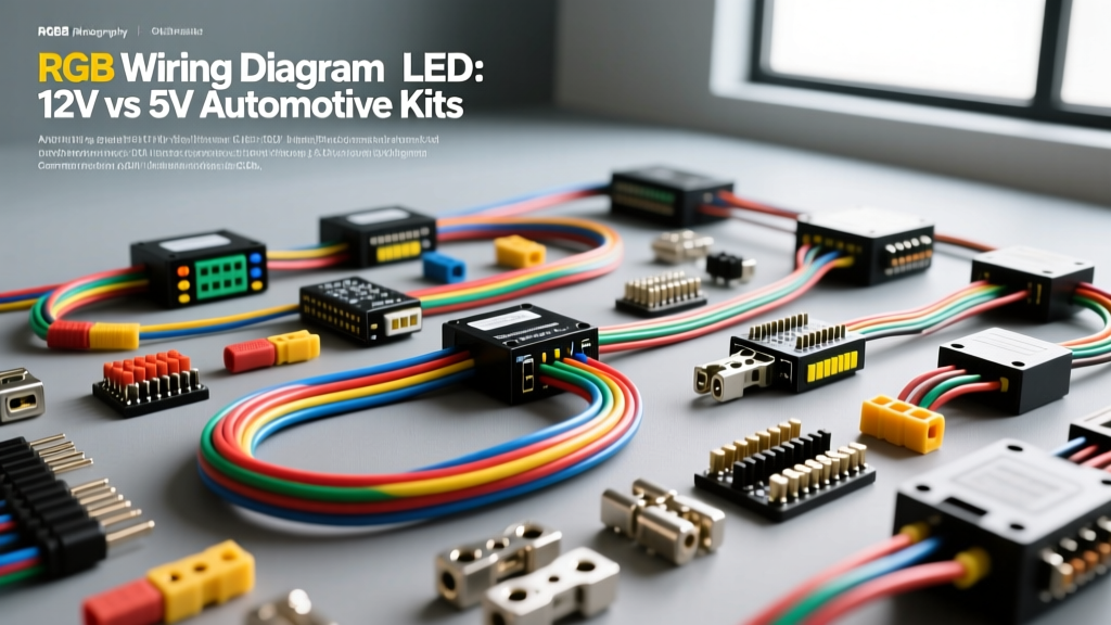
Introduction to Automotive RGB Lighting Systems
Upgrading a vehicle's interior ambient lighting or exterior underglow requires more than just plugging in a generic kit. When searching for a reliable rgb wiring diagram led setup for automotive applications, installers quickly realize that passenger vehicles present unique electrical challenges. From alternator-induced voltage spikes to CAN bus sensitivity, a standard household LED schematic will fail in a 12V or 24V mobile environment. This guide compares the two dominant architectures—12V Analog Common Anode and 5V Addressable (ARGB)—providing the exact wire gauge specifications, pinout configurations, and transient protection requirements needed for a professional-grade installation.
Core Architecture: 12V Analog vs. 5V Addressable RGB
The fundamental difference in any automotive rgb wiring diagram led project lies in how the light-emitting diodes are driven and controlled. Selecting the wrong architecture for your specific vehicle application will result in severe voltage drop, blown MOSFETs, or parasitic battery drain.
12V Analog Common Anode Systems
Traditional 12V RGB strips utilize a common anode design. The positive 12V rail is shared across all LED nodes, while the Red, Green, and Blue cathodes are individually grounded by the controller's internal MOSFETs to mix colors.
- Connector Type: 4-Pin JST-SM (2.54mm pitch) or waterproof Deutsch DT series for exterior runs.
- Wire Color Code Standard: Pin 1: White (+12V), Pin 2: Green, Pin 3: Red, Pin 4: Blue.
- Current Draw: Typically 1.2A to 1.5A per meter at full white (all channels active).
- Limitation: Entire strip segments must change color simultaneously; no chasing or per-node addressing.
5V Addressable (ARGB) Automotive Systems
Addressable RGB strips (often utilizing WS2812B or SK6812 chipsets) embed a microcontroller inside every single LED node. Because these chips operate strictly at 5V logic and power, integrating them into a 14.4V running automotive electrical system requires a dedicated DC-DC buck converter.
- Connector Type: 3-Pin JST-SM. Never plug a 3-pin 5V ARGB connector into a 4-pin 12V RGB header, as this will instantly destroy the 5V data ICs.
- Wire Color Code Standard: Pin 1: Red (+5V), Pin 2: Green (Data/DIN), Pin 3: Black/White (GND).
- Current Draw: Up to 3.0A per meter at peak white (60 LEDs/meter).
- Automotive Requirement: Requires an automotive-grade 12V-to-5V step-down module with overvoltage and reverse polarity protection.
Controller Selection & Pinout Specifications
The brain of your rgb wiring diagram led setup dictates how the system interfaces with the vehicle. Below is a comparison of standard automotive controller architectures and their respective pinout requirements.
| Controller Type | Input Voltage | Pinout Configuration | Signal Output | Best Application |
|---|---|---|---|---|
| Bluetooth BLE 12V | 9V - 15V DC | 4-Pin (12V, GND, DAT, SYNC) | PWM (400Hz) | Interior footwells, trunk lighting |
| RF 2.4GHz 5V ARGB | 5V DC (via Buck) | 3-Pin (5V, GND, DIN) | SPI/PWM (800KHz) | Grille lighting, chasing underglow |
| CAN Bus Integrated | 12V (OBD2 Tapped) | OBD2 Pins 4, 5, 6, 14, 16 | CAN High/Low + 12V PWM | OEM-style interior ambient sync |
When utilizing a CAN bus controller to sync lighting with vehicle events (e.g., flashing red upon unlocking, or matching the infotainment screen color), you must tap into the OBD2 port. Pin 6 is CAN High, Pin 14 is CAN Low, Pin 16 is constant 12V, and Pins 4/5 are chassis grounds. Always use a 120-ohm termination resistor if extending the CAN bus wiring beyond 30 centimeters to prevent signal reflection and U-code communication faults.
Power Tapping & AWG Selection Guide
The most common point of failure in aftermarket automotive lighting is undersized wiring and poor splice connections. According to SAE J1128 standards for low-tension primary cable, wire gauge must be selected based on the maximum continuous current draw and the total length of the circuit (both positive and ground returns).
Voltage Drop & Wire Sizing Chart
Automotive systems operate between 12.6V (engine off) and 14.4V (alternator charging). A voltage drop exceeding 3% will cause visible flickering in RGB LEDs and erratic controller reboots.
| Total Circuit Length (ft) | Max Draw: 5A (Interior) | Max Draw: 15A (Underglow) | Max Draw: 30A (Heavy Duty) |
|---|---|---|---|
| 0 - 10 ft | 18 AWG | 14 AWG | 10 AWG |
| 11 - 20 ft | 16 AWG | 12 AWG | 8 AWG |
| 21 - 30 ft | 14 AWG | 10 AWG | 6 AWG |
Step-by-Step Fuse Box Integration
Avoid using "T-taps" or "scotch locks." These cut through the wire strands, inviting corrosion and creating high-resistance points that trigger modern Body Control Module (BCM) open-circuit faults. Instead, use the following methodology:
- Locate an Ignition-Switched Fuse: Use a digital multimeter to find a fuse slot in the interior cabin panel that reads 0V with the key off, and 12V with the ignition in the "ON" or "ACC" position.
- Install an Add-A-Circuit Fuse Tap: Insert the tap into the switched slot. The original circuit fuse goes into the slot closest to the plug pins, and a new 5A or 10A MINI II fuse goes into the top slot to protect the RGB controller.
- Route the Power Wire: Run the primary 14 AWG or 16 AWG power wire from the fuse tap to the controller location, securing it every 8 inches with nylon cable ties to prevent chafing against sharp metal edges.
- Establish a Clean Ground: Remove the paint or powder coating from a bare metal chassis bolt near the controller. Sand the ring terminal, apply dielectric grease after tightening, and torque to the vehicle manufacturer's specification (typically 8-12 Nm for M6 bolts).
- Seal All Splices: Use adhesive-lined, dual-wall heat shrink tubing (3:1 shrink ratio) on all crimp connections to prevent moisture ingress, which is critical for exterior rgb wiring diagram led applications.
Transient Protection & Grounding
Vehicle electrical systems are notoriously noisy. When the alternator's voltage regulator switches, or when heavy inductive loads (like radiator fans or AC clutches) disengage, transient voltage spikes (load dump) can exceed 40V for several milliseconds. As outlined in SEMA Garage integration guidelines, sensitive 5V ARGB controllers and Bluetooth modules will be permanently damaged without protection.
To safeguard your rgb wiring diagram led installation, wire a Transient Voltage Suppressor (TVS) diode in parallel with the main power input of the controller. An SMAJ15A TVS diode is ideal for 12V systems, clamping any spike above 15V safely to ground. Additionally, ensure that the ground wire for the LED strips returns to the same chassis ground point as the controller to prevent ground loops, which manifest as alternator whine in the audio system or a rolling "wave" effect across the LED strip.
Troubleshooting Common Automotive RGB Failures
- Symptom: LEDs flicker rapidly when the engine is running.
Cause: Alternator ripple voltage exceeding the controller's smoothing capacitors, or a loose chassis ground.
Fix: Install a 2200µF 25V electrolytic capacitor across the 12V and GND inputs of the controller, and verify the ground connection resistance is below 0.05 ohms. - Symptom: ARGB strip shows incorrect colors or random flashing nodes.
Cause: Data line voltage drop or electromagnetic interference (EMI) from spark plug wires.
Fix: Inject 5V power into the data-in (DIN) end of the strip. Route the data wire at least 6 inches away from ignition coils and use a shielded twisted-pair cable for the data signal. - Symptom: Vehicle battery dies overnight (Parasitic Draw).
Cause: Controller wired to a constant 12V source without a low-voltage cutoff, or a MOSFET leaking current in the off state.
Fix: Rewire the main power feed to an ignition-switched Add-A-Circuit, or install an automotive relay triggered by the ignition switch to physically sever power to the RGB system when parked. - Symptom: BCM throws a "Bulb Out" warning on the dash.
Cause: Tapping into OEM dome light or footwell circuits without matching the impedance of the original halogen bulb.
Fix: Add a dummy load resistor (e.g., 12-ohm, 10W ceramic resistor) in parallel with the LED tap to satisfy the BCM's cold diagnostic pulse checks.
Mastering the nuances of an automotive rgb wiring diagram led project bridges the gap between a messy, unreliable DIY job and a premium, OEM-plus lighting upgrade. By respecting AWG limits, implementing TVS protection, and utilizing proper fuse taps, your lighting system will withstand the harsh realities of the automotive electrical environment for years to come. For further reading on primary cable insulation and temperature ratings, refer to the Delphi Automotive Electrical Systems documentation.