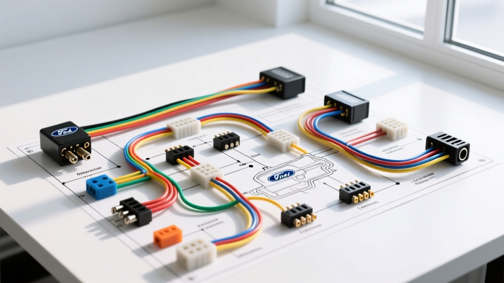
Introduction: Why Upgrade the Ford 8N to 12 Volts?
The Ford 8N, produced between 1947 and 1952, is one of the most iconic agricultural machines in history. Originally equipped with a 6-volt, positive-ground electrical system, these tractors often struggle with cold-weather cranking, dim lighting, and compatibility with modern implements. Converting your 8N to a 12-volt, negative-ground system is the most impactful modification you can perform. This comprehensive guide provides the exact 12 volt wiring diagram for 8N Ford tractor applications, detailing the transition from the original 6V generator to a modern 12V alternator, updating the ignition circuit, and reversing the ground polarity.
Whether you are restoring a barn find or upgrading a daily working tractor, adhering to modern SAE J1128 Low Tension Primary Cable specifications ensures your wiring harness can handle the electrical load without voltage drop or thermal failure.
Core Components for the 12V Conversion Project
Before cutting a single wire, gather the following OEM-equivalent and aftermarket upgrade components:
- Alternator: GM 10SI 1-Wire Alternator (63A or 94A output). The 1-wire design eliminates the need for an external voltage regulator and exciter wire routing.
- Battery: Group 25 or 26 12V Lead-Acid or AGM Battery (Minimum 600 CCA).
- Ignition Coil & Ballast: Retain the original front-mount dash coil but install a 1.2 to 1.5-ohm ceramic ballast resistor. Alternatively, replace it with a true 12V internal-resistor coil.
- Starter Solenoid: 12V, 4-post isolated ground heavy-duty solenoid (prevents chassis grounding issues common on rusted tractor frames).
- Wiring & Terminals: SAE J1128 GXL cross-linked polyethylene wire, adhesive-lined heat shrink, and pure copper ring/spade terminals.
Step-by-Step 12 Volt Wiring Diagram for 8N Ford Tractor
Phase 1: Ground Polarity Reversal
The original 8N system is positive ground. Modern 12V systems are negative ground. Failure to reverse the polarity will instantly destroy the diodes in your new alternator and cause the ammeter to read backwards.
- Disconnect the original 6V battery. Remove both battery cables.
- Clean the chassis ground point on the engine block and the battery box tray using a brass wire brush to ensure bare metal contact.
- Install a new 4 AWG Black cable from the battery negative (-) terminal to the engine block ground boss. Torque to 50 in-lbs.
- Reverse the two posts on the back of the dash-mounted ammeter. This swaps the current flow direction so the needle will correctly swing to 'Charge' when the alternator is producing current.
- Reverse the primary wires on the ignition coil (the wire from the ignition switch must now go to the positive terminal, and the distributor wire to the negative terminal).
Phase 2: Alternator Installation (GM 10SI 1-Wire)
The GM 10SI alternator is the gold standard for tractor conversions due to its internal regulation and robust low-RPM output.
- Remove the original 6V generator and external voltage regulator. Cap off the old regulator wires to prevent accidental shorting.
- Install the 10SI alternator using a custom lower mounting bracket and an adjustable upper tensioning strap. Torque the mounting bolts to 25 ft-lbs.
- Run a 10 AWG Orange wire from the alternator's large BAT terminal (post #2) directly to the battery side of the ammeter, or directly to the starter solenoid battery post. Use a 5/16-inch ring terminal and adhesive heat shrink.
- Technical Note: On a 1-wire setup, the alternator requires a momentary RPM spike (usually above 1,200 engine RPM) to 'excite' and begin charging. If your tractor idles very low, you may need to wire a 10-ohm, 2-watt resistor in parallel with an ignition-switched 'idiot light' connected to terminal #1 to force excitation at idle.
Phase 3: Ignition System & Ballast Resistor Wiring
Early Ford 8N tractors (1947-1950) feature a unique front-mount distributor with the coil mounted directly on the dashboard. The original 6V coil will burn up rapidly if fed direct 12V current. You must step down the voltage.
- Mount a 1.5-ohm ceramic ballast resistor on the dash or firewall near the ignition switch.
- Run a 14 AWG Yellow wire from the 'BATT' terminal of the ignition switch to one side of the ballast resistor.
- Run a second 14 AWG Yellow wire from the other side of the ballast resistor to the 'BAT' terminal on the dash-mounted coil.
- Connect a 14 AWG Black wire from the 'DIST' terminal on the coil to the front-mount distributor terminal block.
- Verify that the coil's negative terminal is connected to the distributor to complete the negative-ground circuit.
Phase 4: Starter Solenoid and Lighting Upgrades
While the original 6V starter motor can survive on 12V for short cranking intervals (it will spin significantly faster), the starter solenoid must be upgraded to handle the 12V coil pull-in current.
- Mount the new 12V 4-post solenoid to the starter motor housing or a clean chassis point.
- Connect a 4 AWG Red cable from the battery positive (+) to the solenoid's large input stud.
- Connect a 4 AWG Red cable from the solenoid's large output stud to the starter motor terminal.
- Wire the ignition switch 'START' terminal to the solenoid's small 'S' activation post using 12 AWG Red wire.
- Lighting: Replace all 6V sealed beam headlights and bulb elements with 12V equivalents (e.g., H6024 12V halogen or LED tractor work lights). LEDs draw roughly 15W compared to the 50W draw of old halogens, drastically reducing alternator load.
8N Ford 12V Conversion Wiring Specification Chart
Reference this chart to ensure your wire gauges and connectors meet the electrical demands of the modified Ford 8N system. Undersized wiring is the leading cause of tractor electrical fires and parasitic voltage drops.
| Circuit Function | SAE Wire Color | AWG Size | Connector Type | Max Load / Notes |
|---|---|---|---|---|
| Battery to Solenoid | Red | 4 AWG | 3/8" Ring Terminal | 300A+ Cranking Surge |
| Alternator Output | Orange | 10 AWG | 5/16" Ring Terminal | 65A - 94A Continuous |
| Ignition Switch to Ballast | Yellow | 14 AWG | 1/4" Spade / Ring | 4A Primary Ignition |
| Coil to Distributor | Black | 14 AWG | 1/4" Spade | Front-mount terminal block |
| Solenoid Activation | Red | 12 AWG | 5/16" Ring Terminal | Solenoid coil draw |
| Headlight Feed | Blue | 12 AWG | Weather-pack / Spade | 10A per lamp (Halogen) |
Troubleshooting Common 12V Conversion Failures
Even with a perfect 12 volt wiring diagram for 8N Ford tractor models, real-world modifications often introduce variables. Use this diagnostic decision tree to resolve common post-conversion issues:
- Symptom: The tractor will not shut off when the ignition key is turned to OFF.
Cause: Alternator backfeeding the ignition circuit. This happens if a 3-wire alternator is used and the 'exciter' wire is tied directly to the coil side of the ballast resistor without a blocking diode or indicator lamp.
Fix: Install a 1N4004 blocking diode in the exciter wire line, or switch to a true 1-wire alternator setup where the BAT terminal is isolated from the ignition switch. - Symptom: The ignition coil becomes too hot to touch after 10 minutes of running.
Cause: Missing or bypassed ballast resistor. The original 6V coil is receiving a full 14.2V from the alternator, saturating the primary windings and causing thermal runaway.
Fix: Verify continuity across the ceramic ballast resistor. It should read between 1.2 and 1.5 ohms on a multimeter. Ensure it is wired in series before the coil. - Symptom: The ammeter reads 'Discharge' while the engine is at high RPM.
Cause: Ammeter posts were not reversed during the positive-to-negative ground swap, OR the alternator drive belt is slipping under load.
Fix: Swap the two 5/16" nuts on the back of the ammeter. If the problem persists, tension the V-belt to 1/2-inch deflection at the midpoint of the longest run.
Authoritative References & Further Reading
When performing electrical modifications on vintage agricultural equipment, always cross-reference your physical harness with factory documentation and established engineering standards. The wiring topology detailed above aligns with the following resources:
- Ford Tractor 8N Service Manual (I&T Shop Manual FO-4): Provides the baseline 6V positive-ground schematic and dash component torque specifications required before initiating the 12V swap.
- SAE J1128 Standard: Dictates the thermal and chemical resistance requirements for low-tension primary automotive and off-road cables, ensuring your GXL wire survives the high-heat environment of the tractor engine bay.
- Yesterday's Tractors (YT) Electrical Archives: An extensive community-verified database of front-mount distributor nuances and GM 10SI bracket fabrication templates specific to the Ford 8N chassis.
By following this structured 12V conversion guide, your Ford 8N will gain the reliable cold-cranking power and modern lighting capabilities necessary for 21st-century farm and estate work, while retaining its classic external appearance.