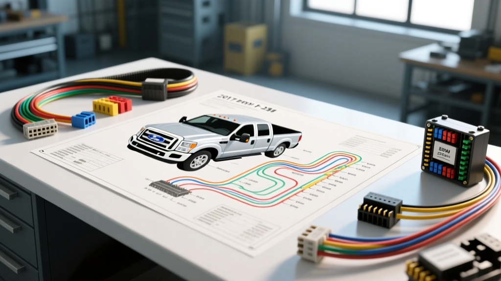
Introduction to the 2017 F-250 Electrical Architecture
The 2017 Ford F-250 Super Duty represents a massive leap in automotive electrical complexity. Whether you are working with the 6.2L V8 gas engine or the 6.7L Power Stroke diesel, the truck relies heavily on a network of modules, including the Body Control Module (BCM) and Powertrain Control Module (PCM). For a beginner, staring at a full factory service manual schematic can feel like reading an alien language. However, understanding the 2017 F250 wiring diagram is entirely manageable if you break it down into fundamental concepts. This guide will teach you how to decode Ford's specific schematic layout, understand OEM wire color codes, and safely trace basic hardwired circuits like the highly popular Upfitter Switches.
Decoding Ford OEM Wiring Schematics
Unlike generic aftermarket diagrams, Ford uses a highly structured, cell-based schematic system. Before you trace a single wire, you must understand the legend and nomenclature used in the factory diagrams.
Cells, Connectors, and Splices
Ford divides its wiring diagrams into numbered 'cells' (usually found in the bottom right corner of the page). These cells group related systems together. When a wire leaves one cell and enters another, the diagram will display a cell-to-cell connector reference.
- Connectors (C): Labeled with a 'C' followed by a number (e.g., C100, C220). The pins inside the connector are numbered sequentially. A label reading C100-12 means Connector 100, Pin 12.
- Splices (S): Labeled with an 'S' (e.g., S140). This indicates a physical solder joint or ultrasonic weld inside the harness where one wire splits into two or more.
- Grounds (G): Labeled with a 'G' (e.g., G100). This is where the circuit completes its path back to the negative battery terminal via the vehicle chassis or engine block.
Ford Wire Color Codes and Abbreviations
Ford does not print full color names on their schematics. Instead, they use standardized two-letter abbreviations. If a wire has a tracer (a stripe), it is denoted by a secondary abbreviation. For example, BN/WH means a Brown wire with a White tracer stripe. Below is a reference chart for the most common colors you will encounter in your 2017 F-250 diagrams.
| Abbreviation | Base Color | Common Application in 2017 F-250 |
|---|---|---|
| BK | Black | Primary Ground / Chassis Return |
| BN | Brown | Upfitter Switches / Trailer Tow |
| BU | Blue | PCM Sensor Signals / CAN-Bus |
| GN | Green | Lighting Circuits / ABS Sensors |
| GY | Gray | Audio / Infotainment Data Lines |
| OG | Orange | Fused Battery Power (Hot at all times) |
| PK | Pink | Ignition Switch Power (Hot in Run/Start) |
| RD | Red | High Amperage Battery Feed |
| VT | Violet | Injector Control / High-Speed Data |
| WH | White | Lighting Returns / Switch Signals |
| YE | Yellow | Airbag Systems (SRS) / BCM Inputs |
Hardwired vs. Multiplex (CAN-Bus) Circuits
As a beginner, it is vital to know which circuits you can safely probe with a standard multimeter and which ones require an oscilloscope. The 2017 F-250 utilizes High-Speed and Medium-Speed Controller Area Network (HS-CAN / MS-CAN) buses to allow modules to talk to one another. SAE J1939 standards dictate much of the heavy-duty CAN architecture.
Beginner Rule of Thumb: Stick to tracing hardwired, high-current circuits first. Headlights, trailer tow relays, and the Upfitter switches use traditional copper pathways. Do not pierce or back-probe CAN-Bus wires (typically twisted pairs in Blue/White or Gray/Orange) with a standard test light, as the voltage spike can destroy the BCM or PCM.
Beginner Walkthrough: Tracing the Upfitter Switch Circuit
The Upfitter Switches (located on the overhead console) are one of the most modified circuits on the 2017 F-250. These switches allow you to power aftermarket lights, winches, or air compressors. Let's trace how this circuit works using the diagram fundamentals.
- The Input: When you press Switch 1 on the overhead console, a low-current signal is sent via a multiplexed LIN-bus wire to the BCM.
- The Logic: The BCM processes the request and triggers an internal solid-state relay.
- The Output: The BCM sends power to the under-hood auxiliary relay box.
- The Blunt-Cut Wires: Under the hood, on the passenger side near the firewall, you will find a bundle of blunt-cut wires taped together. These are your direct outputs.
2017 F-250 Upfitter Switch Pinout and Wire Gauge Table
When connecting aftermarket accessories, you must match your accessory's wire gauge to the OEM output wire to prevent voltage drop and overheating. Refer to this specification chart when terminating your connections.
| Switch ID | Amp Rating | OEM Wire Color | Required AWG Size | Connector Type |
|---|---|---|---|---|
| AUX 1 | 30 Amps | Brown / White (BN/WH) | 10 AWG | Sealed Butt Splice / Deutsch |
| AUX 2 | 30 Amps | Brown / Yellow (BN/YE) | 10 AWG | Sealed Butt Splice / Deutsch |
| AUX 3 | 30 Amps | Brown / Red (BN/RD) | 10 AWG | Sealed Butt Splice / Deutsch |
| AUX 4 | 30 Amps | Brown / Gray (BN/GY) | 10 AWG | Sealed Butt Splice / Deutsch |
| AUX 5 | 40 Amps | Brown / Violet (BN/VT) | 8 AWG | Sealed Butt Splice / Deutsch |
| AUX 6 | 40 Amps | Brown / Orange (BN/OG) | 8 AWG | Sealed Butt Splice / Deutsch |
Pro-Tip: Never use 'vampire taps' or wire piercers on the under-hood upfitter harness. The 2017 F-250 engine bay is subject to extreme temperature swings and moisture. Always use adhesive-lined heat shrink butt connectors or solder-seal terminals to prevent copper oxidation.
Common 2017 F-250 Grounding Points (GND)
A wiring diagram is useless if the ground side of the circuit is compromised. In the 2017 Super Duty, Ford utilizes several critical ground nodes. If you are diagnosing a dim headlight or a no-crank condition, check these physical locations first:
- G100 (Main Battery Ground): Located on the passenger side chassis rail, directly below the battery. This handles the bulk of the vehicle's return current. It uses a massive 1/0 AWG cable.
- G101 (Engine Block Ground): Connects the engine block to the chassis. Crucial for the starter motor and PCM sensor references.
- G200 (PCM Logic Ground): Located on the cylinder head. If this ground corrodes, you will experience erratic transmission shifting and phantom Check Engine Lights (CEL) related to sensor correlation.
How to Perform a Voltage Drop Test on G100
Beginners often test grounds by simply checking for 'continuity' with the power off. This is a flawed method because a single strand of copper wire can show continuity but fail under a 50-amp load. Instead, perform a Voltage Drop Test with the circuit active:
- Set your Digital Multimeter (DMM) to DC Volts.
- Place the red probe on the negative battery terminal (not the clamp, the actual lead post).
- Place the black probe on the metal chassis bolt where G100 attaches.
- Crank the engine or turn on the high-beam headlights.
- A healthy ground will show a voltage drop of less than 0.10V (100mV). If you read 0.50V or higher, the G100 connection is corroded and requires wire brushing and dielectric grease application.
Essential Tools for Tracing F-250 Circuits
To effectively use a 2017 F250 wiring diagram in the real world, you need the right diagnostic equipment. Skip the cheap test lights; they draw too much current and can trigger airbag modules or damage solid-state BCM outputs.
- Automotive Digital Multimeter: The Motorcraft or Fluke 88V is the industry standard. It features a high-impedance input that won't fry sensitive CAN-bus lines and includes a millivolt setting for precise ground testing.
- Back-Probe Pins: Essential for testing connector cavities (like C100) without piercing the wire insulation. These thin steel pins slip past the weather-pack seals to make contact with the brass terminal inside.
- Breakout Boxes: If you need to test the PCM or BCM connectors while they are plugged in, OEM-style breakout boxes allow you to measure pin voltages without damaging the delicate module headers.
Authoritative Resources for Ford Super Duty Schematics
While aftermarket manuals like Haynes or Chilton provide basic overviews, they often lack the cell-by-cell depth required for modern Super Duty trucks. For accurate, factory-level 2017 F250 wiring diagrams, rely on the following authoritative sources:
- Ford Motorcraft Service Manuals: Available via Ford Service Content, these are the exact PDFs used by dealership technicians. They include the complete connector cavity views and splice location maps.
- SAE International Standards: Understanding the underlying architecture of the truck's data networks requires familiarity with SAE J1939 (for heavy-duty CAN communication) and SAE J1113 (for electromagnetic compatibility in automotive wiring).
- OEM Tech Service Bulletins (TSBs): Always check for TSBs related to wiring harness chafing. The 2017 F-250 had a known issue where the main chassis harness could rub against the frame rail near the transmission crossmember, leading to intermittent BCM communication faults.
By mastering the legend, respecting wire gauges, and utilizing proper voltage drop testing, you can confidently navigate the electrical system of your 2017 F-250. Whether you are installing a snow plow, wiring a custom trailer, or diagnosing a parasitic draw, the schematic is your ultimate roadmap.