Introduction to Car Audio Power Delivery
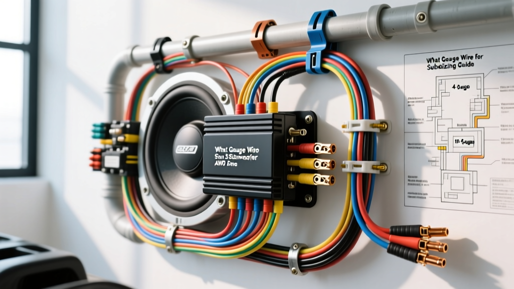
Upgrading your vehicle's bass response requires more than just dropping a new enclosure into the trunk. One of the most common and critical questions in mobile electronics is: what gauge wire for subwoofer amplifiers is required to prevent voltage drop, clipping, and potential fire hazards? Undersizing your power wire restricts current flow, starving your amplifier during heavy bass transients and causing the amp's protection circuitry to constantly engage. Oversizing, while generally safe, adds unnecessary weight, cost, and stiffness, making routing through modern vehicle firewalls a nightmare.
This practical installation guide and gauge reference chart will walk you through calculating your exact amperage draw, selecting the correct American Wire Gauge (AWG), and executing a professional-grade installation that adheres to automotive electrical safety standards.
Calculating Total Current Draw (Amperage)
Before you can determine the correct wire gauge, you must calculate the maximum current your subwoofer amplifier will pull from the vehicle's charging system. Do not rely on the 'Peak Power' or 'Max Power' ratings printed on the box; these are marketing metrics. You must use the RMS (Root Mean Square) continuous power rating.
The Amperage Formula
To find your maximum amperage draw, use the following formula based on your amplifier's class topology:
- Class D Amplifiers (Most modern subwoofer amps): Amperage = (Total RMS Wattage / 13.8V) / 0.75 (Efficiency)
- Class AB Amplifiers (Older or full-range amps): Amperage = (Total RMS Wattage / 13.8V) / 0.50 (Efficiency)
Example: You are installing a 1000W RMS Class D monoblock subwoofer amplifier.
1000W / 13.8V = 72.46A.
72.46A / 0.75 = 96.6 Amps.
You must size your wire to handle at least 100 Amps continuously.
AWG Wire Gauge Sizing Chart for Subwoofers
The chart below dictates the minimum recommended Oxygen-Free Copper (O.F.C.) wire gauge based on your calculated amperage and the total distance from the battery positive terminal to the amplifier's power input. Note that distance includes the ground wire length back to the chassis.
| Amp RMS Wattage | Max Current (Amps) | 0 to 10 Feet | 10 to 15 Feet | 15+ Feet |
|---|---|---|---|---|
| Up to 250W | ~35A | 10 AWG | 8 AWG | 8 AWG |
| 250W - 500W | ~65A | 8 AWG | 6 AWG | 4 AWG |
| 500W - 1000W | ~100A | 4 AWG | 4 AWG | 2 AWG |
| 1000W - 1500W | ~150A | 2 AWG | 1/0 AWG | 1/0 AWG |
| 1500W - 2500W | ~250A | 1/0 AWG | 2/0 AWG | 2/0 AWG |
| 2500W+ | 300A+ | 2/0 AWG | 3/0 AWG | 4/0 AWG |
O.F.C. vs. CCA: The Material Matters
When asking what gauge wire for subwoofer setups is best, the material is just as important as the number. Oxygen-Free Copper (O.F.C.) is the automotive standard. Copper-Clad Aluminum (CCA) is a cheaper alternative found in budget kits, but aluminum has roughly 61% the conductivity of copper. If you are forced to use CCA wire, you must increase the wire gauge by one full size (e.g., use 2 AWG CCA where 4 AWG O.F.C. is specified) to maintain safe ampacity ratings and prevent the wire from melting under load.
Step-by-Step Power Wire Installation Guide
Step 1: Battery to Firewall Routing
Disconnect the negative battery terminal before beginning. Route your main power wire from the battery positive terminal, through the firewall, and down the vehicle's door sill. Crucial Rule: Never run your main power wire on the same side of the vehicle as your RCA signal cables. Keep power on the driver's side and RCA/speaker wires on the passenger side to prevent alternator whine and electromagnetic interference (EMI). Use a rubber grommet when passing through the firewall to prevent the metal from slicing the wire insulation and causing a dead short.
Step 2: Primary Fusing (ANL vs. AGU)
Install a primary fuse within 12 inches of the battery positive terminal. This fuse protects the vehicle from catching fire if the main power wire shorts to the chassis. For subwoofer amplifiers pulling over 60 Amps, use an ANL fuse with a corresponding ANL fuse holder. AGU glass fuses are prone to shattering under high-vibration, high-current bass transients and should be avoided for main power lines exceeding 60A.
Step 3: Grounding the Amplifier (The Most Critical Step)
A poor ground is the number one cause of subwoofer amplifier clipping, thermal shutdown, and alternator whine. Your ground wire must be the exact same AWG and material as your power wire, and kept as short as possible (under 3 feet).
- Locate a solid, structural piece of bare metal on the vehicle chassis.
- Use a wire brush or sandpaper to aggressively remove all paint, primer, and clear coat down to bare, shiny steel.
- Crimp a heavy-duty copper ring terminal onto your ground wire and seal it with adhesive-lined heat shrink.
- Secure the ring terminal using a grade-8 steel bolt, a star washer (to bite into the metal and prevent vibration loosening), and a lock nut. Do not use self-tapping sheet metal screws; they do not provide sufficient surface area for high-current grounding.
Speaker Wire vs. Power Wire: Don't Confuse the Two
While power wire delivers 12V DC current from the battery, speaker wire delivers amplified AC audio signals from the amp to the subwoofer voice coils. Because subwoofers require massive current to move heavy cones, undersized speaker wire will dampen the amplifier's control over the driver, resulting in 'muddy' or loose bass.
| Subwoofer RMS Power | Recommended Speaker Wire Gauge | Connector Type |
|---|---|---|
| Up to 300W | 14 AWG | Spade Terminals / Bare Wire |
| 300W - 800W | 12 AWG | Spade Terminals / Banana Plugs |
| 800W - 1500W | 10 AWG | High-Current Spade / Set Screws |
| 1500W+ | 8 AWG | Set Screw Terminals / Ring Terminals |
The 'Big Three' Upgrade for High-Draw Subwoofers
If your calculated amperage draw exceeds 150 Amps (roughly 1500W+ RMS), your vehicle's stock wiring cannot handle the return current from the alternator to the battery. You must perform a 'Big Three' electrical upgrade using 1/0 AWG O.F.C. wire:
- Alternator Positive to Battery Positive: Supplements the factory charging wire.
- Engine Block to Chassis: Improves the grounding path for the alternator and starter.
- Battery Negative to Chassis: Ensures the battery can effectively discharge high current to the vehicle's ground plane.
For vehicles with high-output alternators (200A+), upgrading to 2/0 AWG for the Big Three is highly recommended to minimize voltage drop across the engine bay.
Common Installation Mistakes and Troubleshooting
- Symptom: Amplifier goes into protect mode during heavy bass hits.
Cause: Voltage drop due to undersized power/ground wire or a loose ground connection.
Fix: Check ground resistance with a multimeter (should be under 0.05 ohms). Upgrade to a larger AWG wire if voltage drops below 11.5V at the amp terminals during play. - Symptom: Alternator whine in the audio signal.
Cause: Ground loop or power/signal wire interference.
Fix: Ensure RCA cables are routed on the opposite side of the vehicle from the power wire. Verify the head unit and amplifier share a common, clean ground reference. - Symptom: Main fuse blows immediately upon connection.
Cause: Dead short to ground.
Fix: Inspect the firewall grommet and under-seat routing for pinched insulation. Never bypass a blown fuse with a higher-rated fuse or a piece of foil.
Authoritative References
For further reading on automotive electrical standards and mobile electronics installation best practices, consult the following resources:
- SAE International J1128 Standard - Specifications for low-tension primary automotive cables and temperature ratings.
- Crutchfield Car Audio Wiring Guide - Comprehensive retailer guidelines on amplifier wiring kits and gauge matching.
- Mobile Electronics Association - Industry standards for professional car audio installation and electrical safety.