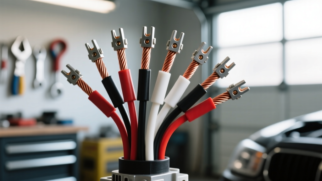
Understanding 26 Gauge Wire in Automotive Networks
In modern automotive electrical systems, 26 gauge wire (AWG 26) is rarely used for power delivery. Instead, it is the backbone of low-current, high-sensitivity data and signal networks. You will typically find 26 AWG utilized in Controller Area Network (CAN) bus lines, Local Interconnect Network (LIN) bus circuits, Supplemental Restraint System (SRS) clock springs, Hall-effect camshaft/crankshaft sensor signals, and 5-volt reference circuits for MAP and TPS sensors. Because of its microscopic cross-sectional area, 26 AWG is highly susceptible to micro-fractures, capillary moisture wicking, and terminal fretting corrosion.
Troubleshooting these micro-gauge circuits requires a fundamental shift in diagnostic strategy. Using a standard incandescent test light on a 26 AWG circuit will draw upwards of 1.5 amps, instantly melting the copper strands or destroying the ECU driver transistor. This guide outlines a strict, step-by-step troubleshooting flow designed specifically for the physical and electrical limitations of 26 gauge wire.
26 AWG Technical Specifications Chart
Before probing any circuit, a technician must understand the baseline physical and electrical properties of the wire. The following specifications align with standard copper conductors and SAE J1128 low-tension primary cable standards for thin-wall (TXL/GXL) automotive insulation.
| Parameter | Specification (AWG 26) | Diagnostic Significance |
|---|---|---|
| Conductor Diameter | 0.0159 in (0.405 mm) | Extremely fragile; piercing probes will sever strands. |
| Cross-Sectional Area | 0.129 mm² (253 Circular Mils) | Equivalent to metric 0.13 mm² AVSS wire. |
| Resistance (@ 20°C) | 40.81 Ω per 1,000 ft | High resistance per foot; long runs suffer significant voltage drop. |
| Max Ampacity (Chassis) | 1.3 Amps | Strictly for signal/data; never for inductive loads or solenoids. |
| Typical Insulation | TXL, GXL, AVSS | Thin-wall to reduce harness weight; vulnerable to abrasion. |
Step-by-Step Troubleshooting Flow for 26 AWG Circuits
When diagnosing communication faults (e.g., U0100 Lost Communication) or sensor rationality codes on micro-gauge wiring, follow this sequential flow to isolate the fault without introducing secondary damage.
Phase 1: Symptom Isolation & Scan Tool Triage
Never begin with a multimeter. Begin with the data stream. If diagnosing a CAN bus fault on 26 AWG wires (typically OBD2 DLC Pins 6 and 14), check the scan tool for module dropout patterns.
- Single Module Dropout: Indicates a localized spur-line fault or connector issue at the specific module.
- Multiple Module Dropouts (U-Codes): Indicates a main trunk-line fault, termination resistor failure, or a short to ground on the 26 AWG CAN-H or CAN-L lines.
Record the freeze frame data and note if the fault correlates with steering wheel movement (clock spring), engine vibration (sensor pigtail), or HVAC operation (blower motor EMI interference).
Phase 2: Non-Destructive Visual & Physical Inspection
Because 26 AWG wire has a cross-section of only 0.129 mm², it is prone to fatigue breakage inside the insulation. The copper can snap while the TXL insulation remains perfectly intact.
- The Massage Test: With the ignition ON and engine OFF (KOEO), gently massage and bend the 26 AWG wire harness near the sensor or ECU connector while monitoring live data. A sudden spike or dropout in the 5V reference or signal return confirms an internal micro-fracture.
- Connector Pin Drag Test: Disconnect the ECU and sensor. Using a spare, unused male terminal (e.g., TE Connectivity MCON 0.50 series), insert it into the female 26 AWG terminal. You should feel a distinct, crisp detent. If it slides in with zero resistance, the terminal tensioning fingers are fatigued, causing high-resistance fretting corrosion.
- Capillary Wicking Check: Inspect the wire loom for signs of green/white copper oxide. If moisture enters a damaged connector, it will wick down the 26 AWG strands via capillary action, causing high resistance deep inside the harness.
Phase 3: Micro-Ohm Continuity & Voltage Drop Testing
Standard continuity beepers are insufficient for 26 AWG data lines. A circuit can pass the 10-ohm threshold of a continuity beeper but still fail to transmit a high-speed CAN signal.
- Set DMM to Millivolts/Auto-Ranging Ohms: Measure the end-to-end resistance of the 26 AWG wire. For a standard 15-foot run from the ECU to a wheel speed sensor, the baseline resistance should be approximately 0.6 Ω (15 ft x 40.81 Ω / 1000 ft).
- Load the Circuit Safely: If you must voltage-drop test a 5V reference circuit, use a high-impedance digital multimeter (>10 MΩ). Never use a test light. Back-probe the connector using a dedicated T-pin or micro back-probe. Never use a piercing probe; puncturing the thin-wall GXL insulation of a 26 AWG wire guarantees future moisture ingress and strand severing.
- Evaluate the Drop: A voltage drop greater than 0.1V on a 5V reference circuit carrying 50mA indicates severe terminal corrosion or a partially broken 26 AWG strand.
Phase 4: Oscilloscope Signal Validation
For CAN, LIN, or digital Hall-effect signals on 26 AWG wire, an oscilloscope is mandatory.
- CAN Bus Setup: Connect Channel A to CAN-H and Channel B to CAN-L. Set timebase to 10 µs/div and voltage to 2V/div.
- Analyze the Waveform: CAN-H should idle at 2.5V and spike to 3.5V. CAN-L should idle at 2.5V and drop to 1.5V. If the 26 AWG wire has a high-resistance fault, the square waves will exhibit rounded edges (RC time constant distortion) and fail to reach peak voltage thresholds, causing intermittent communication DTCs.
Common 26 AWG Failure Modes & Real-World Fixes
1. Steering Column Clock Spring Fatigue (SRS & LIN Bus)
The clock spring utilizes ultra-thin flat ribbon cables or tightly coiled 26 AWG (or smaller) wires to maintain continuity to the steering wheel airbag, horn, and steering angle sensor (LIN bus). Constant left-to-right rotation causes work-hardening of the copper. Fix: Clock springs cannot be safely repaired due to SRS liability and precise rotational centering requirements. Replace the entire clock spring assembly and perform the steering angle sensor recalibration via the OEM scan tool.
2. 5-Volt Reference Circuit Micro-Corrosion
Many OEMs use 26 AWG or 24 AWG for the 5V reference line shared between the MAP, TPS, and APP sensors. If the connector seal fails, micro-corrosion adds 5 to 10 ohms of resistance. At 100mA of draw, this drops the ECU's 5.0V reference down to 4.0V at the sensor, triggering a rationality code (e.g., P0107 MAP Circuit Low). Fix: Clean terminals with electronic contact cleaner and a nylon micro-brush. Apply dielectric grease (specifically formulated for micro-connectors, like TE Connectivity's recommended Nyogel) to the seal, not the contact face, to prevent future oxidation.
3. CAN Bus Chafing at Firewall Pass-Throughs
The main CAN trunk line often passes through the firewall grommet. Over time, engine torque roll causes the harness to rub against the sheet metal, wearing through the thin GXL insulation of the 26 AWG CAN-H/CAN-L wires and shorting them to ground. Fix: Repair the chafed section using OEM-spec micro-splicing. Do not use twist-and-tape methods.
Proper Repair Techniques for Micro-Gauge Wiring
Repairing 26 gauge wire requires specialized tools and materials. Standard butt connectors will not crimp onto a 0.129 mm² conductor securely.
- Solder Seal Sleeves: For emergency or non-flexing harness repairs, use adhesive-lined solder seal sleeves. The heat-shrink outer layer provides a waterproof seal, while the low-temperature solder ring melts to bond the fragile 26 AWG strands without the mechanical stress of a hard crimp.
- Micro-Crimping: For terminal replacements, use a ratcheting micro-crimp tool calibrated for 0.13 mm² / 26 AWG wire. The crimp must pass a pull-test (typically 15-20 Newtons for micro-terminals) to ensure the wire insulation and conductor are both properly captured by the terminal bellmouthish.
- Splicing Best Practices: When splicing 26 AWG wire, use a staggered inline splice or a Western Union splice folded flat, covered by dual-wall adhesive heat shrink. Never bundle 26 AWG splices directly next to each other, as the bulk will prevent the harness from bending, leading to new fatigue points.
By adhering to this step-by-step diagnostic flow and respecting the physical limitations of 26 gauge wire, technicians can accurately isolate micro-circuit faults without introducing secondary failures into highly sensitive automotive networks. For deeper architectural insights into multiplexed data lines, consult the Bosch Automotive Technology reference guides on CAN and LIN protocol physical layers.