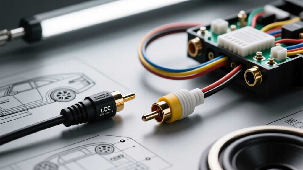
The High-Level vs. Low-Level Signal Mismatch
When integrating an aftermarket amplifier into a vehicle with a factory head unit or OEM amplified system, installers frequently face a critical interface challenge: extracting a clean audio signal. Factory systems output high-level speaker signals, while aftermarket amplifiers require low-level RCA inputs. Attempting to directly splice RCA cable to speaker wire without proper signal conditioning will result in severe voltage clipping, impedance mismatches, and catastrophic failure of the amplifier’s input operational amplifiers (op-amps).
Speaker wire typically carries amplified alternating current (AC) ranging from 10V to 40V+ at a low impedance (4 ohms or 2 ohms). Conversely, RCA cables are designed for unamplified line-level signals, usually peaking between 2V and 5V at a high impedance (10,000 ohms or more). This guide compares the products and methods used to safely bridge this gap, with a specific focus on the mechanical and electrical execution of splicing heavy-gauge speaker wire to micro-gauge RCA conductors.
Product Comparison: Methods to Splice RCA Cable to Speaker Wire
Selecting the correct interface depends on the factory amplifier’s topology, the presence of digital signal processing (DSP), and the physical gauge of the wiring harness. Below is a comparison of the three primary product categories used for this conversion.
| Product Type | Best Application | Signal Quality | Gauge Compatibility | Avg. Cost |
|---|---|---|---|---|
| Active LOC (Line Output Converter) | Factory Class-D amps, DSP systems, All-Speed audio | Excellent (Restores bass roll-off) | 18 AWG - 10 AWG Inputs | $50 - $150 |
| Passive LOC (Transformer-based) | Standard aftermarket head units, basic OEM audio | Good (Slight insertion loss) | 16 AWG - 12 AWG Inputs | $15 - $30 |
| High-Level RCA Pigtails (Resistive) | Amps with built-in high-level auto-sense inputs | Fair (Prone to noise if unshielded) | 18 AWG - 14 AWG Inputs | $10 - $25 |
1. Active Line Output Converters (LOC)
Active LOCs, such as the AudioControl Matrix or LC2i series, utilize powered operational circuitry to read the high-level speaker signal, step down the voltage, and output a clean, buffered low-level RCA signal. Crucially, modern active LOCs feature “load generation” resistors. Many late-model vehicles (e.g., GM Bose, Ford Sony systems) use Class-D factory amplifiers that check for speaker impedance before outputting audio. An active LOC mimics a 4-ohm speaker load, preventing the factory amp from muting the signal.
2. Passive Line Output Converters
Passive LOCs use audio transformers to step down the voltage. While they do not require a 12V remote turn-on or power ground, transformers introduce insertion loss and can saturate if the factory head unit outputs more than 15V RMS. They are best reserved for basic, non-amplified factory head units where the speaker wire gauge is a standard 16 AWG or 14 AWG.
3. High-Level to RCA Adapter Cables
These are simple RCA cables with bare speaker wire pigtails at the opposite end, sometimes containing basic inline resistors. They are only recommended if your aftermarket amplifier explicitly features “High-Level Inputs” with internal summing and step-down circuitry. Splicing these directly to a standard RCA input will destroy the amp.
The Gauge Challenge: Splicing 14 AWG to 22 AWG
The most overlooked aspect of this installation is the physical wire gauge transition. Automotive speaker wire typically ranges from 16 AWG to 12 AWG (stranded oxygen-free copper). The internal signal conductor of a standard RCA cable is incredibly thin, usually 24 AWG to 22 AWG. Furthermore, the RCA cable features a delicate braided or foil shield that must be managed to prevent alternator whine.
According to SAE J1128 standards for automotive low-tension primary cable, improper mechanical joining of disparate wire gauges leads to high-resistance joints, localized heating, and signal degradation. Here is the professional execution for splicing these gauges:
The Step-Down Solder and Marine Shrink Method
- Prepare the RCA Cable: Strip back 2 inches of the RCA outer jacket. Fold the braided copper shield back over the jacket and twist it into a single pigtail. This shield is your RCA ground. Strip 1/4 inch of insulation from the 22 AWG center signal conductor.
- Prepare the Speaker Wire: Strip 1/2 inch of insulation from the 14 AWG speaker wire. Separate the strands into two equal groups, creating a “Y” shape.
- The Lineman’s Wrap: Place the tiny 22 AWG RCA conductor against one side of the 14 AWG “Y”. Wrap the 14 AWG strands tightly around the 22 AWG wire, then fold the 22 AWG wire back over the 14 AWG strands to lock it in place. This prevents the thin wire from snapping under vibration.
- Solder and Seal: Flow rosin-core electronics solder into the joint. Once cooled, slide a piece of dual-wall adhesive-lined polyolefin heat shrink over the joint. The inner adhesive melts and seals out moisture and copper-oxide corrosion, which is critical in high-humidity environments like door panels and kick panels.
Shielding Topology and Ground Loops
When you splice RCA cable to speaker wire, you are introducing a new ground path via the RCA shield. If the RCA shield is grounded at both the factory head unit (via the speaker wire negative) and the aftermarket amplifier chassis, you create a ground loop. This loop acts as an antenna, picking up electromagnetic interference (EMI) from the vehicle’s alternator and ignition system, resulting in a high-pitched whine that rises with engine RPM.
The Fix: The RCA shield must be grounded at the source (the LOC or head unit end) and left floating (disconnected) at the amplifier end. Many premium RCA cables feature a directional arrow printed on the jacket indicating the source-grounded end. Ensure the twisted shield pigtail from your splice is securely grounded to the LOC’s dedicated ground terminal, not just spliced into the speaker wire’s negative return.
Vehicle-Specific Wiring & Color Codes
Identifying the correct speaker wires before splicing is critical. Factory harnesses rarely use standard aftermarket color codes. Below are common high-level signal wire colors for popular OEM systems where an LOC is required:
- GM (Bose Amplified, 2014-2022 Silverado/Sierra): Front Left (+) Tan, (-) Gray; Front Right (+) Light Green, (-) Dark Green. Note: These systems utilize active noise cancellation (ANC) and All-Speed warning chimes. An Active LOC with ANC filtering (like the AudioControl LC7i) is mandatory to prevent chime feedback loops.
- Ford (Sony System, 2015-2020 F-150): Front Left (+) White, (-) White/Black; Front Right (+) Gray, (-) Gray/Black. Ford uses a center-point steering wheel microphone for ANC; splicing into the front channels without an LOC that supports chime retention will disable safety warnings.
- Chrysler/Dodge (Alpine System, Ram 1500): Front Left (+) Gray, (-) Gray/Dark Green. These systems often use digital Class-D amplification. A standard passive transformer LOC will result in zero bass output due to the factory DSP’s frequency-dependent volume scaling.
Troubleshooting Common Installation Failures
If you have completed the splice and are experiencing audio anomalies, consult this diagnostic tree:
- Symptom: Severe Alternator Whine. Cause: RCA shield is grounded at the amplifier, creating a loop. Fix: Cut the RCA shield ground wire at the amplifier input and isolate it with heat shrink.
- Symptom: Audio Cuts Out at High Volume. Cause: The factory amp’s protection circuit is tripping because the passive LOC or direct splice lacks a proper impedance load. Fix: Upgrade to an Active LOC with load-generation resistors (typically 45-ohm 10W resistors wired in parallel across the high-level inputs).
- Symptom: No Bass, Only Mid/High Frequencies. Cause: Factory DSP applies a high-pass crossover and bass roll-off to the speaker wires to protect small OEM door speakers. Fix: Use an Active LOC with built-in bass restoration circuitry (e.g., AccuBASS) to digitally reconstruct the low-frequency AC waveform before sending it to the RCA outputs.
Final Execution Notes
Successfully adapting high-level speaker outputs to low-level RCA inputs requires more than just twisting wires together. By selecting the correct Active or Passive LOC for your specific vehicle’s DSP topology, executing a proper step-down solder joint between 14 AWG and 22 AWG conductors, and maintaining strict single-point shield grounding, you ensure a noise-free, high-fidelity signal transfer to your aftermarket amplification.