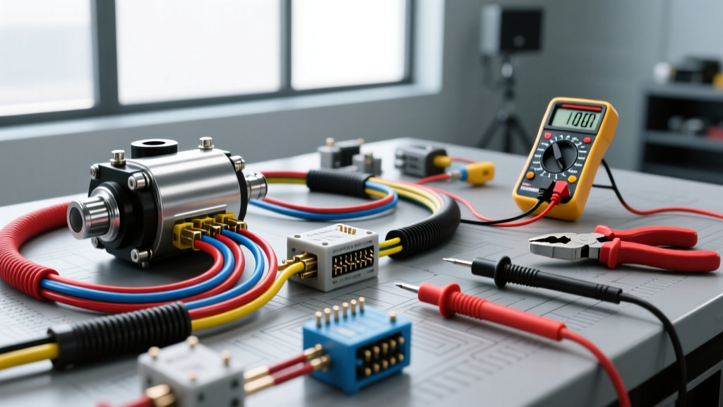
The True Cost of Diagnosing Fuel Pump Electrical Problems
When a vehicle cranks but won't start, or experiences intermittent stalling under load, the fuel delivery system is the primary suspect. However, blindly replacing the fuel pump assembly—a job that can cost upwards of $600 in parts and labor—is a costly mistake if the root cause lies in the wiring harness, relay, or inertia switch. Accurately diagnosing fuel pump electrical problems requires a methodical approach and specific diagnostic tools. This analysis breaks down the exact equipment required, the associated costs for DIY versus professional diagnosis, and the technical specifications needed to verify circuit integrity.
Essential Diagnostic Tools and Cost Breakdown
To isolate fuel pump electrical problems from mechanical pump failures, you must verify that the pump is receiving adequate voltage and current under load. A standard test light is insufficient for modern high-current fuel pump circuits.
1. True RMS Digital Multimeter (DMM) with Min/Max
The cornerstone of electrical diagnosis. You need a DMM capable of measuring DC voltage, resistance, and continuity. Crucially, a Min/Max recording feature is required to catch intermittent voltage drops that occur for only a fraction of a second when the fuel pump relay primes the circuit at key-on.
- Budget Option: AstroAI DM6000AR or similar True RMS meter ($45 - $65).
- Professional Option: Fluke 87V Industrial Multimeter ($450 - $500).
- Requirement: CAT III or CAT IV safety rating for probing automotive fuse blocks.
2. High-Current Pinned Probes and Back-Probes
Fuel pump connectors, such as the standard Delphi/Packard 2-way or 4-way sealed connectors found on GM and Ford tanks, require specific back-probes to measure voltage while the circuit is live. Piercing wire insulation with standard probes introduces moisture and guarantees future corrosion.
- Cost: $25 - $45 for a comprehensive set of T-pin and flat blade back-probes.
3. ISO Micro Relay Test Jumper / Bypass Tool
Most modern vehicles use a standard 4-pin or 5-pin ISO micro relay for the fuel pump control module. A relay bypass tool allows you to safely jumper pins 30 (B+) and 87 (Load) to force the pump on without dismantling the relay box.
- Cost: $15 - $20 for a fused relay bypass jumper set.
4. Low-Amp Current Clamp (Hall Effect)
To diagnose a failing pump motor drawing excessive current (which causes wiring overheating and PCM driver shutdown), a low-amp inductive clamp connected to an oscilloscope or advanced DMM is necessary.
- Cost: $120 - $180 for a reliable Hall-effect clamp (e.g., Pico TA018).
Total DIY Tool Investment: $105 (Basic) to $750 (Professional)
DIY vs. Professional Diagnostic Cost Comparison
Understanding the financial implications of diagnosis helps justify the investment in proper tooling. Dealerships and independent shops rely on a 'verify, then replace' protocol.
| Diagnostic Phase | DIY Cost (Time & Tools) | Professional Shop Cost | Risk Factor |
|---|---|---|---|
| Initial Relay & Fuse Verification | $0 (Using DMM / Test Light) | $120 - $150 (1 hr diag fee) | Low |
| Voltage Drop & Wiring Harness Test | $0 (Assuming DMM ownership) | Included in diag fee | Medium (Risk of misreading voltage drop) |
| Fuel Pressure & Volume Test | $40 (Rental) or $60 (Purchase) | Included in diag fee | High (Fuel spill hazard) |
| PCM/Driver Module Scanning | $30 (Basic OBD2) to $300 (Bi-directional) | Included in diag fee | Low |
| Total Upfront Diagnostic Cost | $70 - $400 (Tool dependent) | $150 - $250 (Flat Rate) | N/A |
While a shop charges a flat diagnostic fee, their primary advantage is access to factory wiring diagrams and bi-directional scan tools capable of commanding the fuel pump control module (FPCM) to cycle at specific duty cycles. For the DIYer, the AutoFlowWire database provides the critical pinouts and wire color codes necessary to replicate factory-level diagnostics.
Technical Execution: Voltage Drop Testing the Fuel Pump Circuit
The most common cause of fuel pump electrical problems is not a broken wire, but high resistance in a connector or ground point. According to SAE International standards and leading OEM service manuals, a healthy high-current fuel pump circuit should exhibit a total voltage drop of no more than 0.2V to 0.3V under full load.
Step-by-Step Voltage Drop Procedure
- Preparation: Set the DMM to DC Volts. Connect the red probe to the battery positive terminal and the black probe to the fuel pump power wire at the tank connector (back-probing the sealed connector).
- Circuit Activation: Turn the ignition to the 'ON' position to trigger the 2-3 second fuel pump prime, or jumper the fuel pump relay pins 30 and 87 to run the pump continuously.
- Reading the Positive Side: The DMM should read less than 0.2V. If it reads 1.5V or higher, you have high resistance in the positive feed—often caused by a corroded inertia switch, a melted relay socket, or a degraded splice in the underbody harness.
- Testing the Ground Side: Move the red probe to the fuel pump ground wire at the tank, and the black probe to the battery negative terminal. Activate the pump. Again, the reading must be under 0.2V.
ISO Relay Pinouts and Wire Gauge Specifications
To properly test the control side of the circuit, you must understand the standard ISO micro relay pin configuration utilized in 90% of modern internal combustion vehicles. Refer to the Haynes Manual Relay Testing Guide for foundational relay logic.
| Relay Pin | Function | Typical Wire Gauge (AWG) | Expected Voltage / State |
|---|---|---|---|
| 30 | Constant B+ (Power Feed) | 12 AWG or 14 AWG | 12.2V - 12.6V (Always Hot) |
| 87 | Normally Open (Load to Pump) | 14 AWG or 16 AWG | 0V (Rest) / 12V+ (Active) |
| 85 | Coil Ground / PCM Control | 18 AWG or 20 AWG | Ground path switched by PCM |
| 86 | Coil Power (Ignition/B+) | 18 AWG or 20 AWG | 12V+ (Ignition or Run/Start) |
Common Failure Mode: The Melted Relay Socket
Fuel pumps draw between 7 to 12 amps continuously, and up to 18 amps during the initial prime. If the female terminals inside the fuse box relay socket lose their tension (terminal spread), the resulting high resistance generates immense heat. This melts the plastic ISO socket, fusing the relay in place. When diagnosing fuel pump electrical problems, always pull the relay and inspect the socket cavity for brown scorch marks or deformed plastic. Repairing this requires a pigtail splice kit and a proper micro-terminal crimping tool, not just twisting wires together.
Advanced Diagnostics: Fuel Pump Control Modules (FPCM)
Vehicles manufactured after 2010 largely abandoned simple relay-based full-speed pumps for returnless systems managed by a Fuel Pump Control Module. The FPCM uses Pulse Width Modulation (PWM) to vary pump speed based on engine demand.
- The Diagnostic Challenge: A standard DMM will show a fluctuating, seemingly incorrect voltage (e.g., 6.5V) on the pump feed wire because it is reading the duty cycle average, not a direct short or open.
- The Tool Requirement: An automotive oscilloscope (like a PicoScope 2204A, costing ~$160) is required to view the PWM square wave.
- Specification: A healthy FPCM PWM signal typically operates at 5kHz to 10kHz. A 50% duty cycle equates to roughly 6V average on a DMM, while a 100% duty cycle (wide open throttle demand) will show a solid 12V-14V line on the scope.
Summary: Investing in Accurate Troubleshooting
Fuel pump electrical problems are rarely as simple as a blown fuse. They involve high-current loads, sensitive PCM drivers, and harsh underbody environments. By investing $100 to $200 in a quality True RMS multimeter, a set of back-probes, and a relay bypass tool, you can confidently perform voltage drop tests and isolate the exact point of failure. This prevents the unnecessary replacement of $400 pump assemblies and ensures the vehicle's electrical system is restored to OEM specifications.