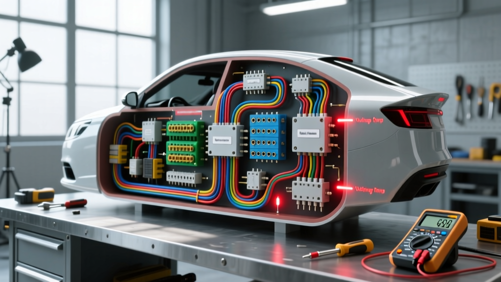
The Fallacy of the Ohmmeter in Automotive Diagnostics
When technicians attempt to diagnose complex wiring faults, the most common mistake is relying on basic continuity testing. If you want to master how to fix electrical problems in cars, you must abandon the ohmmeter for load-bearing circuits. An ohmmeter applies a negligible amount of current (usually less than 5 milliamps) to measure resistance. A single, frayed strand of 18 AWG copper wire can easily pass this microscopic current and display a near-zero ohm reading, tricking the technician into believing the circuit is healthy. However, when that same circuit is asked to carry 15 amps to power a fuel pump or an ABS modulator, the single strand will act as a massive resistor, choking the current and causing a system failure.
To accurately assess circuit health, the circuit must be evaluated under a live load. This is where advanced voltage drop testing becomes the definitive diagnostic protocol. According to Fluke's Automotive Testing Guidelines, voltage drop testing measures the exact amount of electrical pressure (voltage) consumed by a component, a wire, or a connection while the circuit is actively operating.
The Physics and Protocol of Voltage Drop Testing
Voltage drop is the application of Ohm's Law (V = I x R) in real-time. In a standard 12V automotive system, the battery provides the electromotive force. Every connection, terminal, and length of wire possesses inherent resistance. The goal of voltage drop testing is to measure the voltage difference between two points in a live circuit to identify unwanted resistance.
Step-by-Step Fuel Pump Circuit Analysis
Consider a late-model vehicle with a cranking, no-start condition. The fuel pump relay clicks, but fuel pressure is zero. Here is the advanced diagnostic sequence:
- Verify Source Voltage: Set your Digital Multimeter (DMM) to the DC Volts scale. Place the red probe on the battery positive terminal and the black probe on the fuel pump power wire (back-probing the connector). You should read within 0.2V of the battery's resting voltage (e.g., 12.4V).
- Test the Ground Side Drop: Move the red probe to the fuel pump ground wire (back-probing) and the black probe to the battery negative terminal. Activate the circuit. A healthy ground circuit will show less than 0.1V drop.
- Test the Power Side Drop: Place the red probe on the battery positive terminal and the black probe on the fuel pump power wire. Activate the circuit. The DMM will display the voltage 'lost' pushing current through the relays, fuses, and 10 AWG wiring. Anything above 0.3V indicates high resistance in the power feed.
Voltage Drop Threshold Specification Chart
To fix electrical problems accurately, you must know the acceptable limits for different circuit architectures. The following thresholds are based on SAE standards and OEM engineering specifications for 12V systems.
| Circuit Type | Typical Wire Gauge (AWG) | Max Allowable Drop (Power Side) | Max Allowable Drop (Ground Side) | Common Failure Points |
|---|---|---|---|---|
| High Current (Starter/Alternator) | 4 AWG to 1/0 AWG | 0.50V | 0.20V | Corroded battery lugs, frayed braided ground straps |
| Medium Current (Fuel Pump, Headlights) | 10 AWG to 14 AWG | 0.30V | 0.15V | Fuse box internal bussing, Metri-Pack 280 terminals |
| Low Current (Sensors, Solenoids) | 16 AWG to 20 AWG | 0.10V | 0.05V | ECU connector micro-fretting, spliced harness joints |
| CAN Bus / Multiplex Networks | 20 AWG to 24 AWG (Twisted Pair) | N/A (Measured as Differential) | N/A | Terminating resistors, water intrusion in splice packs |
Troubleshooting Decision Tree: Symptom to Root Cause
Use this logical framework to isolate faults without resorting to the 'parts cannon' approach.
- Symptom: Headlights dim severely when the radiator fan engages.
Cause Analysis: The fan motor is pulling excessive amperage, or the shared ground node (e.g., GM G100 series ground) is saturated due to corrosion.
Actionable Fix: Perform a voltage drop test on the fan motor ground. If >0.2V, clean the chassis ground ring terminal and apply conductive anti-oxidant paste. If the ground is perfect, test the fan motor amperage draw; a seized bearing will spike the draw, collapsing system voltage. - Symptom: Intermittent ABS module communication loss (U0121 code) only on rough roads.
Cause Analysis: Mechanical vibration is breaking a compromised connection. This is classic terminal fretting or a broken wire inside the insulation.
Actionable Fix: Back-probe the ABS module CAN High and CAN Low pins. Monitor the DMM while physically manipulating the harness 6 inches from the connector. A sudden spike in resistance confirms a broken copper core beneath intact PVC insulation.
Deep Dive: CAN Bus Network Architecture and Fault Isolation
Modern vehicles utilize Controller Area Network (CAN) bus systems to transmit data. Diagnosing network faults requires understanding differential signaling. As outlined by AA1Car's CAN Bus Diagnostic Library, the system relies on two wires: CAN High (CAN H) and CAN Low (CAN L).
OBD-II DLC Pinout and Terminating Resistor Verification
The most accessible diagnostic access point for the High-Speed CAN network is the OBD-II Data Link Connector (DLC) located under the dashboard.
- Pin 6: CAN High (Typically 2.5V resting, spikes to ~3.5V during dominant state)
- Pin 14: CAN Low (Typically 2.5V resting, drops to ~1.5V during dominant state)
The 60-Ohm Rule: A properly functioning HS-CAN bus requires exactly two 120-ohm terminating resistors placed at the physical ends of the network topology to prevent signal reflection. Because these resistors are wired in parallel, measuring the resistance between Pin 6 and Pin 14 of the DLC (with the battery disconnected) must yield exactly 60 ohms. If you read 120 ohms, one module is offline or a resistor is open. If you read near 0 ohms, the CAN H and CAN L wires are shorted together, often due to chafing where the harness passes through the firewall grommet.
Micro-Corrosion and Fretting in Modern Connectors
When learning how to fix electrical problems in cars built after 2010, you will frequently encounter micro-fretting. This occurs when microscopic vibrations between mated male and female terminals (such as in a Delphi Metri-Pack 150 connector) wear away the tin or silver plating, exposing the base copper to oxygen. The resulting copper oxide is a semiconductor; it allows low-current multimeter continuity tests to pass but blocks high-frequency data signals or high-amperage loads.
The Fix: Never simply spray contact cleaner and reassemble. The oxide layer must be mechanically removed using a specialized terminal burnishing tool or a fiberglass scratch pen. Once cleaned, the terminals must be coated with a dielectric grease specifically formulated for electrical contacts (which contains microscopic conductive particles) to displace oxygen and prevent future oxidation, while ensuring the wire crimp barrel is sealed with heat-shrink tubing to prevent capillary action from drawing moisture into the harness.
Summary of Advanced Diagnostic Discipline
Fixing automotive electrical problems requires moving beyond simple test lights and continuity beepers. By enforcing strict voltage drop thresholds, understanding the differential physics of CAN bus networks, and recognizing the mechanical realities of terminal fretting, you can isolate the exact millimeter of a failing circuit. Always test under load, measure the differential, and trust the physics of the voltage drop.