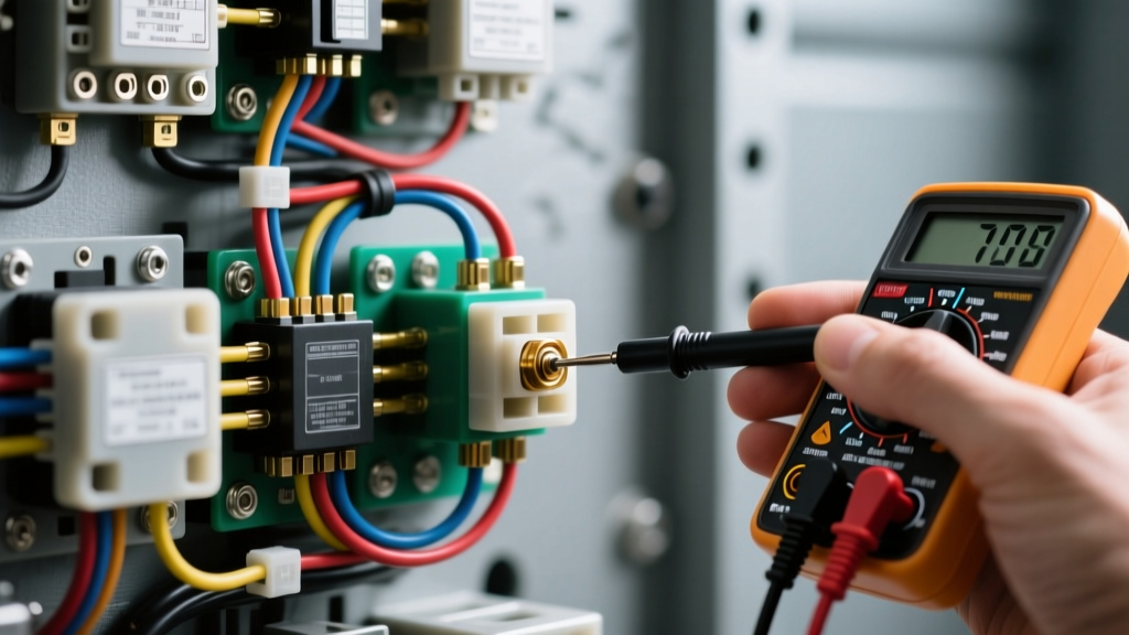
The True Cost of Diagnosing Automotive Relays
When a critical system like your fuel pump, cooling fan, or horn suddenly fails, the root cause is frequently a faulty electromechanical relay. Dealerships and independent repair shops typically charge a diagnostic fee ranging from $150 to $250 just to identify a failed $15 component. Understanding how to check car relays with a multimeter is one of the highest-ROI skills an automotive DIYer or fleet technician can acquire. However, executing this test properly requires more than just a cheap voltage checker; it demands specific tool capabilities to avoid false positives that can lead to misdiagnosed wiring harnesses or unnecessary PCM replacements.
This guide breaks down the exact tool requirements, the hidden costs of relay diagnostics, and the step-by-step methodology for testing standard ISO mini and micro relays found in 90% of modern vehicles.
Tool Cost & Capability Matrix
Not all digital multimeters (DMMs) are created equal when it comes to automotive fault-finding. Below is a cost and capability analysis of the tools required for accurate relay diagnosis.
| Tool Category | Estimated Cost | Relay Testing Suitability | Limitations & Risks |
|---|---|---|---|
| Entry-Level DMM (e.g., AstroAI, generic auto-parts store brands) | $15 - $35 | Poor to Fair | Slow continuity beep response; resistance thresholds often set too high (>30Ω), masking high-resistance faults in load contacts. |
| Mid-Range Automotive DMM (e.g., Innova 5610, Fluke 88V) | $150 - $350 | Excellent | Fast continuity response (<10ms); precise low-ohm resolution for voltage drop testing across pins 30 and 87. |
| Power Probe / Relay Test Bench | $150 - $500 | Superior for Active Testing | Eliminates the need for jumper wires and battery access, but does not replace a DMM for precise voltage drop measurements. |
| OEM Fused Jumper Wire Kit (12 AWG & 18 AWG) | $25 - $45 | Mandatory for Load Testing | Requires fabrication; using unbuilt/unfused wire risks melting harnesses or frying the PCM driver circuit. |
Essential Tool Requirements & Fabrication Costs
To properly test a relay, you must verify both the control circuit (the electromagnetic coil) and the load circuit (the high-current switch). According to the AA1Car Relay Diagnostics library, testing the coil alone is insufficient; carbon tracking and pitting on the internal switch contacts can cause severe voltage drops under load, starving components like fuel pumps of necessary amperage.
The Fused Jumper Wire Harness
You cannot test the load contacts of a relay without applying a physical load. Back-probing the relay socket with a multimeter will only show continuity, not current-carrying capacity. You must fabricate or purchase a fused jumper harness.
- Load Circuit Jumpers (Pins 30 & 87): Must be constructed using 12 AWG TXL automotive wire to handle 30A-40A loads without introducing parasitic resistance. Cost: ~$15 for a spool. Must include an inline 20A or 30A ATC fuse holder ($5).
- Control Circuit Jumpers (Pins 85 & 86): 18 AWG wire is sufficient for triggering the coil, which typically draws only 100mA to 150mA. Cost: ~$8.
- Terminals: Standard Bosch weather-pack or Metri-Pack female terminals ($10 for an assortment) are required to interface safely with the OEM fuse box without bending the delicate socket pins.
Step-by-Step: How to Check Car Relays With a Multimeter
The following procedure applies to the ubiquitous DIN 72552 standard 5-pin Bosch-style relay. The pins are numbered on the base of the relay: 85 (Coil Ground), 86 (Coil Power), 30 (Common Power In), 87 (Normally Open), and 87a (Normally Closed).
Phase 1: Testing the Electromagnet Coil (Pins 85 & 86)
- Remove the relay from the vehicle's power distribution center (PDC).
- Set your multimeter to the Ohms (Ω) setting, preferably the 200Ω range for maximum resolution.
- Place the probes on Pins 85 and 86. Polarity does not matter for standard DC coils.
- Expected Reading: A healthy 12V automotive relay coil will read between 50Ω and 120Ω. For example, a standard 40A ISO mini relay typically measures around 75Ω ± 10%.
- Fault Diagnosis: An "OL" (Open Loop) reading indicates a broken internal coil wire. A reading below 10Ω indicates a shorted coil, which will blow the vehicle's control circuit fuse or damage the PCM driver transistor.
Phase 2: Verifying Switch Contacts (Pins 30, 87, 87a)
- Switch the multimeter to Continuity mode (the diode/soundwave icon).
- Test Pins 30 and 87a (Normally Closed). The meter should beep instantly, displaying a resistance of less than 0.5Ω.
- Test Pins 30 and 87 (Normally Open). The meter should read "OL" (no continuity).
- Note on Cheap Multimeters: If your meter's continuity threshold is set to beep at anything under 30Ω, it may fail to alert you to pitted contacts that read 15Ω. Always look at the actual resistance number, not just the beep.
Phase 3: Active Load & Voltage Drop Testing (The Professional Method)
As outlined by the Fluke Automotive Relay Testing Guide, a relay might click and show continuity, but still fail under real-world amperage. To test this, you must perform a voltage drop test.
- Connect your 18 AWG jumper wires to Pins 85 (Ground) and 86 (12V Battery Positive). You should hear an audible click as the coil energizes.
- While the relay is energized, connect your 12 AWG fused jumper wire from the Battery Positive to Pin 30.
- Connect a dummy load (such as a 50W headlight bulb or a high-amp power resistor) from Pin 87 to Ground.
- Set your multimeter to DC Volts (20V range).
- Place the red probe directly on the metal spade of Pin 30, and the black probe directly on the metal spade of Pin 87.
- Expected Reading: The voltage drop across the closed internal contacts should be less than 0.1V. If you read 0.5V or higher, the internal contacts are carbon-tracked or pitted. The relay must be replaced, as it will cause severe voltage starvation to the downstream component.
Vehicle-Specific Wiring & Diagnostic Context
Understanding the wiring harness connected to the relay is crucial when diagnosing why a relay failed. For example, in General Motors LS-platform vehicles (e.g., Silverado, Tahoe), the fuel pump relay circuit typically utilizes the following OEM wire colors and gauges:
- Pin 30 (Power In): Orange wire, 12 AWG (Direct from Battery via Maxi-Fuse)
- Pin 87 (Load Out): Gray wire, 12 AWG (To Fuel Pump)
- Pin 85 (Control Ground): Black wire, 18 AWG (To Chassis Ground Splice Pack)
- Pin 86 (Control Power): Dark Green/White tracer, 18 AWG (From PCM/ECM Driver)
If you find that Pin 86 is not receiving 12V during key-on engine-run (KOER), the fault is not the relay; it is an open circuit in the 18 AWG Dark Green wire or a failed PCM driver. Replacing the relay will not solve the issue, highlighting the importance of systematic multimeter testing over blind parts swapping.
Solid-State Relays: When a Multimeter Isn't Enough
While the Bosch Mobility Automotive Relays catalog still heavily features electromechanical switches, modern vehicles (particularly Ford and late-model European platforms) are increasingly utilizing Solid-State Relays (SSRs) and Pulse Width Modulated (PWM) smart junction boxes for cooling fans and fuel pumps.
SSRs contain internal logic boards and MOSFETs. You cannot test the load contacts of an SSR with a standard multimeter in continuity mode, as the internal semiconductors require a specific gate voltage to close the circuit. Diagnosing an SSR requires a bidirectional OBD2 scan tool capable of commanding the relay active (Cost: $300 - $1,000+) and an automotive oscilloscope to read the PWM duty cycle signals. If your multimeter testing confirms the control wires have proper power, ground, and PCM trigger signals, but an SSR is not passing current, the smart fuse box must be replaced or reprogrammed.
Summary: Is the Dealership Quote Worth It?
Investing $150 in a quality auto-ranging multimeter and $30 in materials to build a proper 12 AWG fused jumper harness pays for itself the very first time you diagnose a stuck cooling fan relay or a dead fuel pump. By mastering how to check car relays with a multimeter—specifically focusing on coil resistance and load-side voltage drop—you bypass the $200 diagnostic fee, avoid the dreaded "parts cannon" approach, and ensure your vehicle's high-amperage circuits are operating at peak electrical efficiency.