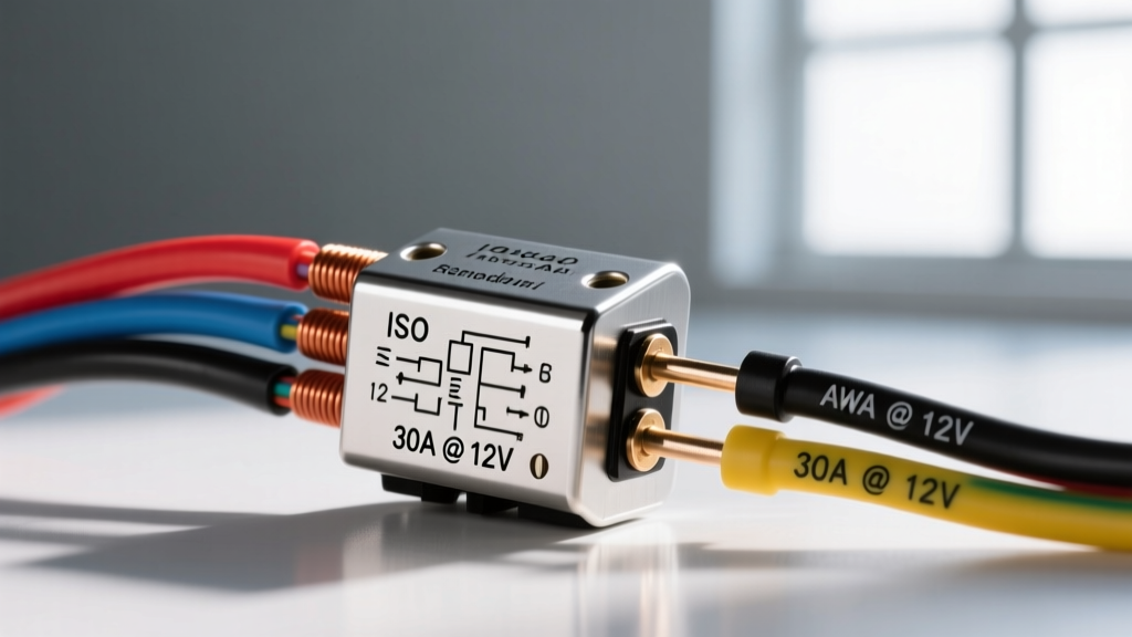
Engineering Standards for the 12 Volt Car Relay
The 12 volt car relay is the fundamental electromechanical switching component in modern automotive lighting and power distribution systems. Governed primarily by ISO 7588 (form factor standards) and DIN 72552 (terminal numbering standards), these devices isolate high-current lighting loads from low-current control switches or ECU transistor drivers. Understanding the exact technical specifications, coil dynamics, and contact metallurgy of these relays is critical for designing reliable light bar harnesses, headlight relay upgrades, and auxiliary fog light circuits.
According to Littelfuse Automotive Relays engineering data, a standard automotive relay must withstand extreme thermal cycling (-40°C to +125°C), severe vibration profiles, and transient voltage spikes inherent to 12V nominal (14.4V alternator-charging) electrical systems.
Physical Form Factors: ISO Mini vs. Micro vs. Standard
Automotive relays are categorized by their physical footprint and terminal blade width. Selecting the correct form factor dictates the relay socket, weather-seal cavity (such as Metri-Pack 280 or Delphi GT series), and maximum current handling.
| Specification | ISO Mini (Standard Cube) | ISO Micro | Standard Bosch (Legacy) |
|---|---|---|---|
| ISO Standard | ISO 7588-1 | ISO 7588-2 | DIN 72552 (Variant) |
| Dimensions (LxWxH) | 25.4 x 25.4 x 25.4 mm | 15.2 x 12.2 x 14.0 mm | 30.0 x 30.0 x 40.0 mm |
| Terminal Blade Width | 6.3 mm x 0.8 mm | 2.8 mm or 4.8 mm | 6.3 mm x 0.8 mm |
| Max Continuous Current | 30A - 40A | 20A - 30A | 30A |
| Typical Application | Headlights, Light Bars, Fuel Pumps | DRLs, Interior Lighting, Horns | Classic Car Restorations |
For high-draw auxiliary lighting (e.g., 50-inch LED light bars pulling 30A+), the ISO Mini with 6.3mm spade terminals is mandatory to prevent terminal overheating and voltage drop across the socket interface.
DIN 72552 Terminal Pinout Configurations
Standardization of pin numbering ensures cross-compatibility between OEM harnesses and aftermarket wiring kits. The DIN 72552 standard dictates the following terminal assignments for the 12 volt car relay:
- Terminal 30 (Common / Line): The primary high-current input from the battery or power distribution block.
- Terminal 87 (Normally Open - NO): The high-current output that receives power when the coil is energized. Used for 95% of automotive lighting applications.
- Terminal 87a (Normally Closed - NC): The high-current output that receives power when the coil is de-energized. Found only on 5-pin (SPDT) relays; used for alarm cutoffs or daytime running light (DRL) logic switching.
- Terminal 86 (Coil Power): The positive trigger input for the electromagnetic coil.
- Terminal 85 (Coil Ground): The negative/ground return path for the electromagnetic coil.
Critical Polarity Warning: Internal Suppression Diodes
Many modern 12 volt car relays contain an internal flyback suppression diode wired in parallel with the coil to protect sensitive ECU drivers from inductive voltage spikes. If a relay contains an internal diode, terminal polarity is strictly enforced. The diode's cathode (stripe) is tied to Terminal 86, and the anode is tied to Terminal 85. If you wire +12V to Terminal 85 and Ground to Terminal 86 on a diode-protected relay, the diode will forward-bias, creating a dead short across the control circuit, which will instantly blow the control fuse or destroy the ECU's low-side driver transistor.
Electrical Specifications & Coil Dynamics
The electromagnetic coil inside a 12V relay is engineered to operate reliably within the fluctuating voltage parameters of a running vehicle. Data from HELLA Electromechanical Relays outlines the following baseline coil specifications for standard 75-Ohm ISO Mini relays:
- Nominal Coil Voltage: 12.0V DC
- Coil Resistance (at 20°C): 75Ω to 90Ω (Tolerance ±10%)
- Steady-State Coil Current: ~140mA to 160mA
- Must Operate (Pull-In) Voltage: ≤ 7.5V DC (Ensures engagement during engine cranking when system voltage drops)
- Must Release (Drop-Out) Voltage: ≥ 1.5V DC (Prevents the relay from remaining stuck closed due to parasitic ECU leakage currents)
- Coil Power Dissipation: ~1.6W to 2.0W
Expert Insight: When driving a relay coil directly from a microcontroller or an ECU's low-side driver (like an Infineon PROFET), the 160mA steady-state current is usually within spec. However, the flyback voltage generated when the magnetic field collapses can exceed 100V. Always specify relays with internal resistors (which dissipate energy safely without polarity restrictions) or external clamping circuits when interfacing with solid-state logic.
Contact Metallurgy and Load Ratings
A common failure mode in lighting harnesses is contact welding, where the relay's internal switch fuses shut. This occurs when the contact material is mismatched to the load type. Automotive lighting loads are not purely resistive; they feature massive inrush currents.
Load Categories & Inrush Multipliers
| Load Type | Examples | Inrush Current Profile | Required Contact Material |
|---|---|---|---|
| Resistive | Heated seats, rear defrosters | 1x Steady State (No spike) | Silver Nickel (AgNi) |
| Tungsten | Halogen headlights, incandescent fog lights | 10x to 15x Steady State (Cold filament resistance is extremely low) | Silver Tin Oxide (AgSnO2) |
| Capacitive / Electronic | LED light bars, HID ballasts | 20x to 50x Steady State (Charging massive input filter capacitors) | Silver Tin Oxide (AgSnO2) with high make-capacity |
| Inductive / Motor | Fuel pumps, cooling fans, winches | 5x to 8x Steady State | Silver Tin Oxide (AgSnO2) |
If you use a cheap relay with AgNi contacts to switch a 50-inch LED light bar that draws 30A steady-state, the initial capacitive inrush can spike to 600A for a few milliseconds. This will arc, pit, and eventually weld the AgNi contacts together, leaving your light bar permanently on even when the switch is turned off. Always source relays explicitly rated for AgSnO2 (Silver Tin Oxide) contacts for LED and Halogen lighting applications.
Wiring Best Practices: AWG Sizing & Insulation
Proper wire gauge selection prevents voltage drop, which directly impacts the lumen output of lighting systems and the thermal integrity of the relay socket. Automotive environments require cross-linked polyethylene insulation (TXL or GXL wire) due to its high heat resistance and thin wall profile.
AWG Wiring Chart for 12V Relay Circuits
| Circuit Segment | Max Current | Recommended AWG (TXL/GXL) | Terminal Crimp Type |
|---|---|---|---|
| Coil Control (85 & 86) | 1A | 16 AWG or 18 AWG | Delphi Metri-Pack 280 / Deutsch |
| Main Feed (Terminal 30) | 30A | 10 AWG | 6.3mm Fully Insulated Spade / Ring |
| Main Feed (Terminal 30) | 40A | 8 AWG | 6.3mm Fully Insulated Spade / Ring |
| Load Output (Terminal 87) | 20A (e.g., Fog Lights) | 12 AWG | 6.3mm Spade / Weather-Pack |
| Load Output (Terminal 87) | 30A (e.g., Light Bar) | 10 AWG | 6.3mm Spade / Weather-Pack |
Voltage Drop Consideration: A 10 AWG wire carrying 30A experiences a voltage drop of approximately 0.1V per foot. If your relay is mounted in the engine bay and the light bar is on the roof rack (15 feet of wire), the round-trip distance is 30 feet, resulting in a 3.0V drop. To maintain optimal LED driver efficiency, upgrade the 87-to-load circuit to 8 AWG for runs exceeding 10 feet.
Real-World Failure Modes & Troubleshooting
When diagnosing a lighting failure, the relay is often blamed, but the root cause usually lies in the surrounding circuit architecture. Use this diagnostic framework:
- Symptom: Relay clicks rapidly (chattering) when engaged.
Cause: Voltage drop on the coil feed circuit (Terminal 86). As the relay engages, the load draws current, dropping system voltage below the relay's 7.5V hold threshold. The relay drops out, voltage recovers, and it pulls in again.
Fix: Upgrade the coil trigger wire to 14 AWG or move the relay trigger source closer to the battery distribution bus. - Symptom: Relay socket is melted around Terminal 30.
Cause: High resistance at the spade terminal interface due to oxidation or using non-ratcheting crimpers on the female disconnects.
Fix: Replace the pigtail socket. Use a high-quality ratcheting crimp tool to ensure gas-tight terminal connections, and apply dielectric grease to the spade blades to prevent galvanic corrosion. - Symptom: ECU fault code for "Short to Ground" on lighting output.
Cause: Using a relay without internal suppression, or wiring a diode-suppressed relay backward, causing the ECU's low-side driver to detect an inductive spike or dead short.
Fix: Verify pin 85/86 polarity with a multimeter. If using an ECU driver, ensure the relay has an internal resistor (not a diode) across the coil, typically rated at 500Ω to 1000Ω, to safely bleed off flyback energy regardless of polarity.
By adhering to ISO dimensional standards, respecting DIN terminal logic, and matching contact metallurgy to the specific inrush profile of your automotive lighting, you ensure a robust, fire-safe, and highly reliable electrical system.