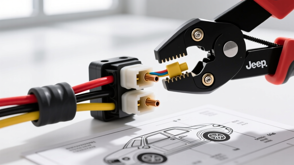
The Hidden Dangers of T-Taps in Modern CAN-Bus Vehicles
When executing an upgrade and modification project on a 2018-2023 Jeep Wrangler JL, integrating aftermarket accessories like LED light bars, winch solenoids, or onboard air compressors requires a reliable 12V trigger source. While many DIYers resort to T-taps, scotch locks, or vampire clips to tap into the factory upfitter switch pigtail, these methods are catastrophic for modern automotive electrical systems. Piercing the wire insulation introduces moisture pathways, leading to galvanic corrosion and severe voltage drops.
Furthermore, the Jeep JL Body Control Module (BCM) utilizes solid-state Field Effect Transistors (FETs) rather than traditional mechanical relays to control the auxiliary circuits. These FETs actively monitor circuit resistance and current draw. If a poorly executed T-tap introduces excessive resistance or a micro-short, the BCM will interpret this as a fault and permanently shut down the auxiliary circuit to protect the wiring harness. The only professional, warranty-compliant method to add new circuits to the OEM upfitter pigtail is by properly crimping and installing new car connector pins directly into the empty cavities of the factory C4 connector.
Identifying the Correct Car Connector Pins for the Jeep JL C4 Harness
The factory upfitter pigtail in the Jeep Wrangler JL terminates in a multi-cavity connector (commonly referred to as the C4 connector). To add your own trigger wires, you cannot simply shove bare wire into the back of the housing. You must source the exact OEM-style terminals. The Jeep JL C4 connector utilizes the Molex MX150 sealed terminal system. This is a high-performance, environmentally sealed connection designed to withstand under-hood temperatures and vibrations.
Selecting the correct car connector pins requires matching the terminal part number to your specific wire gauge. For auxiliary switch triggers, you will typically be using 14 AWG or 12 AWG TXL (Thin-Wall Cross-Linked) primary wire. Sourcing the correct terminals and, crucially, the matching silicone cavity seals is mandatory to maintain the IP67 waterproof rating of the harness.
OEM Upfitter Switch Pinout and Load Specifications
Before adding your car connector pins, you must understand the factory pinout and the specific load limits of the BCM FETs. Refer to the table below to select the correct cavity for your modification project.
| Pin Cavity | Circuit ID | Function | OEM Wire Color | Max Continuous Load | Recommended Mod Wire |
|---|---|---|---|---|---|
| 1 | AUX 1 | Switched 12V Trigger | Violet/White | 15 Amps | 14 AWG TXL |
| 2 | AUX 2 | Switched 12V Trigger | Violet/Orange | 15 Amps | |
| 3 | AUX 3 | Switched 12V Trigger | Violet/Yellow | 40 Amps | 12 AWG TXL |
| 4 | AUX 4 | Switched 12V Trigger | Violet/Green | 40 Amps | 12 AWG TXL |
| 5 | GND | Chassis Ground Reference | Black | N/A | 12 AWG TXL |
Note: When adding a new pin to an empty cavity, you must use the correct mating terminal and seal. For 14 AWG wire, use Molex MX150 terminal part #33012-1021. For 12 AWG, use part #33012-1031.
Mandatory Tooling for Terminal Crimping
You cannot achieve a reliable, gas-tight crimp using generic pliers or Vice-Grips. A proper crimp creates a cold-weld between the copper wire strands and the brass terminal, eliminating oxygen and preventing corrosion. To install these car connector pins correctly, you need specialized tooling:
- Ratcheting Crimp Tool: A dedicated Molex MX150 crimp tool (or a high-precision equivalent like the IWISS SN-28B with the correct jaw die) to ensure both the conductor and insulation wings are crimped to factory specifications.
- Precision Wire Strippers: Calibrated for TXL thin-wall insulation. Standard thick-wall PVC strippers will nick the copper strands of TXL wire, reducing ampacity and creating a failure point.
- Cavity Seal Insertion Tool: Or a small pair of smooth-jawed hemostats to push the silicone MAT (Matrice A Trou) seals into the connector housing without tearing them.
Step 1: Wire Preparation and TXL Insulation Stripping
Cut your 14 AWG or 12 AWG TXL wire to the required length, routing it away from exhaust manifolds and sharp firewall edges. When stripping the wire, you must expose exactly 3.0mm to 4.0mm of bare copper. If you strip too much bare wire, the conductor will protrude past the front of the terminal crimp wings, potentially shorting against adjacent pins inside the connector housing. If you strip too little, the insulation will be caught inside the conductor crimp wings, resulting in a high-resistance connection that will trigger a BCM fault code.
Inspect the stripped strands. They must be perfectly straight and unbent. If the copper strands are twisted or flared, the wire will not seat correctly into the car connector pins, compromising the mechanical pull-strength of the crimp.
Step 2: The Anatomy of a Perfect Crimp
The Molex MX150 terminal features two distinct crimp zones: the forward conductor wings and the rear insulation wings. According to TE Connectivity and industry crimping standards, both zones must be addressed simultaneously by your ratcheting tool.
- Insert the Terminal: Place the bare car connector pin into the correct die of the crimp tool. The conductor wings should sit in the smaller, deeper notch, while the insulation wings rest in the wider, shallower notch.
- Squeeze to Ratchet: Close the tool one click to lightly hold the terminal in place.
- Seat the Wire: Slide the stripped wire into the terminal. The bare copper should completely fill the conductor wings, with the insulation flush against the back of the conductor crimp zone. No bare copper should be visible between the two crimp zones.
- Complete the Crimp: Squeeze the handles fully until the ratchet releases.
Visual Inspection: A perfect conductor crimp will exhibit a slight 'bellmouth' on the rear edge (where the wire enters), preventing the sharp edge of the terminal from shearing the copper strands under vibration. The insulation wings should wrap tightly around the TXL jacket without piercing it. Perform a manual pull-test; the wire should not detach from the terminal under firm hand tension.
Step 3: Cavity Seals and Pin Insertion
Water intrusion is the enemy of any upgrade project. Before inserting your newly crimped car connector pins into the Jeep JL C4 housing, you must install the silicone cavity seals. If you are using a pre-assembled pigtail, slide the individual ribbed seal over the wire and push it forward until it seats into the recessed seal zone of the MX150 terminal.
To insert the pin into the connector housing:
- Locate the empty cavity corresponding to your desired AUX circuit (refer to the pinout table above).
- Align the terminal with the cavity, ensuring the locking tang (the small metal spring tab on the side of the pin) is oriented in the correct direction. On the C4 connector, the locking tangs typically face inward toward the center rib.
- Push the terminal forward until you hear and feel a distinct 'click'. This indicates the locking tang has engaged the plastic retention barb inside the housing.
- Gently tug the wire backward. If the pin pulls out, the tang was bent during crimping. You must discard the pin, cut the wire, and start over with a new terminal.
Step 4: Load Testing and BCM Verification
Once your car connector pins are fully seated and the secondary connector lock (TPA) is snapped into place, it is time to verify the circuit. Do not immediately connect your high-draw accessory. First, connect the negative terminal of the vehicle battery and use the Uconnect infotainment screen to configure your newly populated AUX switch to 'Momentary' or 'Latching' mode, depending on your accessory requirements.
Using a digital multimeter, probe the newly added wire while actuating the switch on the dashboard. You should see a clean, instantaneous jump to 12.2V - 12.6V. Next, connect your relay harness trigger wire. Actuate the switch again and use an inductive DC clamp meter to verify the current draw. If your relay coil draws less than the circuit limit (e.g., under 15A for AUX 1), the BCM will maintain the circuit without throwing a soft fault. By taking the time to properly crimp and seal OEM-style car connector pins, you ensure your modification project is robust, waterproof, and fully integrated with the Jeep's advanced electrical architecture.
For further reading on automotive wire specifications, consult the SAE J1128 standard for Low Tension Primary Cable, which dictates the thermal and chemical resistance requirements for TXL wire used in modern engine bays. Additionally, reviewing the Molex MX150 Application Tooling Specifications will provide exact jaw-die measurements for quality control during your build.