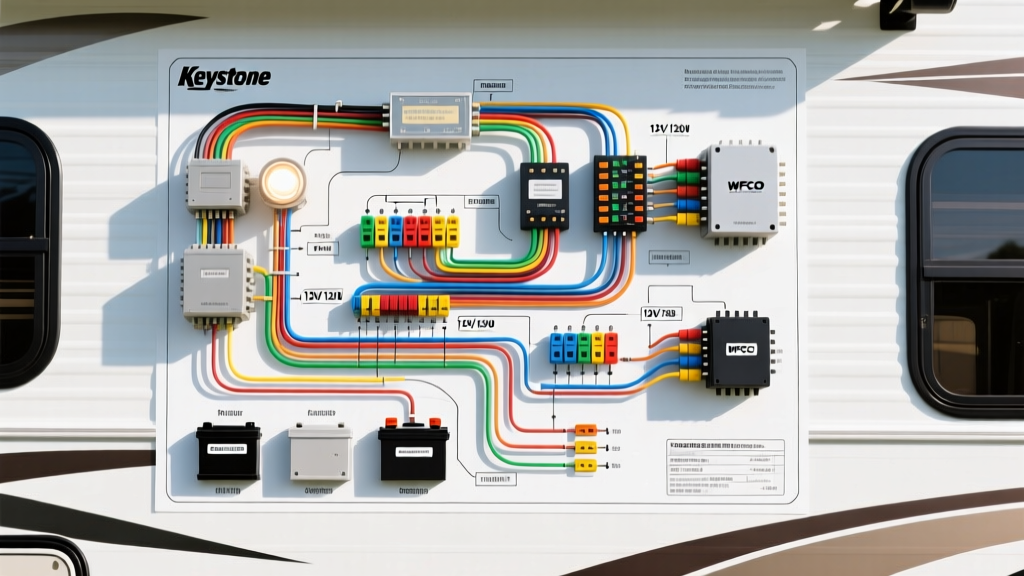
Introduction to Keystone Electrical Architecture
When diagnosing complex electrical faults in modern recreational vehicles, relying on a multimeter alone is insufficient. You must understand the underlying logic of the system. Navigating schematic Keystone RV wiring diagrams requires an advanced understanding of both National Electrical Code (NEC) standards for 120V AC systems and Society of Automotive Engineers (SAE) standards for 12V DC systems. Keystone RV, encompassing popular lines like the Montana, Cougar, Outback, and Hideout, utilizes a hybrid electrical architecture that integrates high-amperage DC distribution with standard residential-style AC branch circuits.
This advanced technical deep dive will dissect the proprietary conventions found in Keystone schematics, trace the critical paths through WFCO and Progressive Dynamics power centers, map the 7-way umbilical junction box, and provide actionable torque and AWG specifications for professional-grade repairs.
Decoding the Schematic: Keystone's Proprietary Conventions
One of the most dangerous pitfalls for technicians transitioning from residential electrical work to RV repair is assuming wire color codes remain consistent across voltage domains. Keystone schematics explicitly separate 120V AC and 12V DC pathways, but older models (pre-2012) occasionally feature overlapping color conventions that can lead to catastrophic short circuits if misinterpreted.
According to the SAE J1128 Low Tension Primary Cable Standard, 12V DC systems utilize specific color coding. However, Keystone's internal manufacturing schematics sometimes adapt these colors based on supplier availability, particularly for ground and neutral returns. Always verify the schematic legend for your specific model year and floorplan.
| Wire Color | 120V AC Function (NEC) | 12V DC Function (SAE/Keystone) | Schematic Trace Notes |
|---|---|---|---|
| Black | Hot (Line) | 12V Hot (Older Models) / Ground (Rare) | Verify voltage domain before cutting. Modern Keystone uses Red for 12V Hot. |
| White | Neutral (Grounded Conductor) | 12V Ground (Chassis Bond) | 12V White must show continuity to the main chassis ground bus bar. |
| Red | Traveler (3-Way Switch) / Unused | 12V Hot (Primary Feed) | Main battery feed to the WFCO DC distribution block. |
| Blue | Traveler / Unused | Electric Brake Feed | Routes directly from the 7-way J-Box to the brake controller output. |
Tracing the 120V AC Main Distribution & WFCO Power Center
The heart of the Keystone 120V AC system is typically a WFCO (e.g., WF-8955) or Progressive Dynamics power center. When reading the schematic, the 120V AC main feed enters the power center via a 50-amp or 30-amp shore power cord, passing through a main breaker before distributing to branch circuits and the integrated converter/charger.
Critical Torque Specifications and AWG Ratings
A common failure mode in Keystone travel trailers is thermal runaway at the main AC lugs due to improper torque. The NFPA 1192 Standard on Recreational Vehicles mandates strict adherence to manufacturer torque specifications to prevent arcing and fire hazards.
- Main 50A Feed Lugs (6 AWG Copper): Torque to 45 in-lbs. Over-torquing will strip the brass terminal threads; under-torquing causes micro-arcing under high inductive loads (like A/C compressor startup).
- Branch Circuit Breakers (10 AWG to 14 AWG): Torque to 20 in-lbs.
- Converter AC Input (10 AWG): Ensure the wire is stripped exactly 3/8" to prevent copper strands from shorting against the adjacent neutral bus bar.
When tracing a "dead" AC outlet on the schematic, locate the specific 15A or 20A breaker. Keystone often daisy-chains outlets using the "Line" and "Load" terminals on GFCI receptacles. If the schematic shows a GFCI protecting downstream standard receptacles, always test the GFCI first before tearing into the walls to trace a broken 14/2 Romex cable.
12V DC Junction Box & 7-Way Blade Integration
The front junction box (J-Box) is the critical nexus where the tow vehicle's 7-way umbilical connector interfaces with the Keystone's internal 12V DC harness. Schematics for this area are vital for diagnosing charging issues, lighting failures, and electric brake faults.
| 7-Way Pin | Function | Umbilical Color | Keystone Internal Harness Color | AWG & Protection |
|---|---|---|---|---|
| 1 | Left Turn / Stop | Yellow | Yellow | 12 AWG / 20A Fuse |
| 2 | 12V Aux / Reverse | Black or Purple | Black (Pre-2015) / Red (Modern) | 10 AWG / 30A Auto-Reset |
| 3 | Ground | White | White (Bonded to Chassis) | 8 AWG or 6 AWG |
| 4 | Right Turn / Stop | Green | Green | 12 AWG / 20A Fuse |
| 5 | Electric Brakes | Blue | Blue | 10 AWG / 40A Breaker |
| 6 | 12V Battery Charge | Red | Red | 10 AWG (Upgrade to 6 AWG recommended) |
| 7 | Running / Marker Lights | Brown | Brown | 14 AWG / 15A Fuse |
Advanced Troubleshooting: Pin 6 Voltage Drop
A frequent complaint among Keystone owners is that the house batteries fail to charge adequately while towing. The schematic will show Pin 6 routing from the J-Box through a 30A or 40A auto-reset circuit breaker, then running up to 35 feet to the main battery bank. Keystone typically uses 10 AWG wire for this run. According to Ohm's law, pushing 15 amps of charging current through 35 feet of 10 AWG copper wire results in a voltage drop of approximately 1.3 volts. If the tow vehicle alternator outputs 13.8V, the Keystone batteries only see 12.5V—barely enough to maintain a charge, let alone bulk charge a depleted bank.
The Fix: Use the schematic to trace the Pin 6 wire path. Bypass the factory 10 AWG wire by pulling a new 6 AWG stranded copper wire through the chassis I-beam, protected by a 50A ANL fuse at the battery terminal, reducing the voltage drop to under 0.4V.
High-Amperage Systems: Slide-Outs and Battery Disconnects
Keystone's larger fifth wheels (Montana, Alpine) utilize heavy-duty Lippert Components (LCI) electric slide-out motors and high-capacity battery disconnect solenoids. These systems draw massive transient currents and are notorious for schematic-tracing challenges.
Tracing the LCI Slide-Out Motor Circuit
The schematic for an LCI slide-out system will show a direct feed from the positive battery bus, passing through a 40A or 50A DC breaker (often a Bussmann Type 180 series), into a heavy-duty solenoid pack, and finally to the motor. The control side of the solenoid is triggered by a low-amperage 12V signal from the interior switch panel.
Diagnostic Decision Tree:
- Symptom: Slide-out switch clicks, but motor does not turn, and main 50A breaker trips immediately.
- Schematic Trace: The click indicates the low-amperage control coil is receiving 12V and closing the high-amperage contacts.
- Fault Isolation: An immediate breaker trip indicates a dead short or a mechanically seized motor drawing infinite stall current. Disconnect the motor leads at the solenoid. Use a multimeter to check resistance across the motor terminals. A healthy LCI motor should read between 0.5 and 1.5 ohms. A reading of 0.0 ohms indicates shorted internal windings; an open loop (OL) indicates burnt internal brushes.
The Battery Disconnect Solenoid Failure Mode
Many Keystone models use a "Salesman's Switch" (battery disconnect) wired through a continuous-duty solenoid located in the front pass-through storage. The schematic reveals that the interior switch only provides a ground path for the solenoid's 12V coil. If the RV has no 12V power despite fully charged batteries, technicians often replace the batteries or the converter. However, tracing the schematic to the solenoid coil will often reveal pitted internal copper contacts. The coil energizes (you hear a faint click), but the high-amperage contacts fail to pass current. Bypass the solenoid temporarily with a heavy-gauge jumper wire to confirm the fault before replacing the solenoid with an upgraded 200A continuous-duty model.
Authoritative References & Standards
For technicians and advanced DIYers working on Keystone RV electrical systems, strict adherence to industry standards is non-negotiable for safety and warranty compliance. Always consult the following resources when modifying or repairing RV wiring:
- NFPA 1192 Standard on Recreational Vehicles: The definitive guide for RV fire and life safety, including strict mandates on wire routing, overcurrent protection, and thermal barriers.
- SAE J1128 Low Tension Primary Cable Standard: Governs the physical and electrical properties of the 12V DC wiring used in Keystone chassis and house systems.
- RV Industry Association (RVIA): Provides certification guidelines and best practices for RV electrical system manufacturing and aftermarket repair protocols.
By mastering the specific conventions, torque requirements, and high-amperage pathways detailed in schematic Keystone RV wiring diagrams, you can elevate your troubleshooting from guesswork to precision engineering.