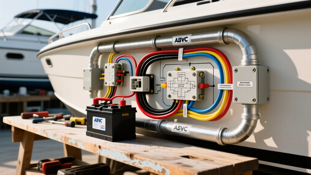
Understanding the Single Battery Boat Wiring Diagram
For owners of center consoles, skiffs, and small day-cruisers, a single battery boat wiring diagram represents the foundational baseline of marine electrical systems. While larger vessels require complex dual-battery or house-bank configurations, a single-battery setup is the perfect starting point for learning marine-grade electrical routing. However, 'simple' does not mean 'forgiving.' The harsh marine environment—characterized by salt spray, constant vibration, and high humidity—demands strict adherence to electrical standards that far exceed typical automotive applications.
A proper single battery boat wiring diagram routes power from the battery to a main battery disconnect switch, then to a positive distribution busbar and a negative ground busbar. From these busbars, individual circuits branch out to bilge pumps, navigation lights, stereo systems, and live wells. By centralizing your connections at heavy-duty busbars rather than stacking ring terminals directly onto the battery posts, you minimize voltage drop, reduce the risk of galvanic corrosion, and make future troubleshooting significantly easier.
Core Components of a Basic Marine Electrical System
- Main Battery Switch: A heavy-duty rotary switch (such as the Blue Sea Systems m-Series 9001e) rated for at least 300A continuous and 1200A cranking. This isolates the battery from the boat's DC system when not in use, preventing parasitic draws and serving as an emergency shutoff.
- Busbars: Tinned copper busbars with 3/8-inch studs. You need one for positive distribution (covered with a red insulating boot) and one for negative returns. A 250A rating is typically sufficient for single-battery skiffs.
- Overcurrent Protection: Panel-mounted circuit breakers or blade-fuse blocks (like the Blue Sea ST Blade series) mounted on the positive feed side of each branch circuit.
Marine vs. Automotive Wire: The ABYC Standard
The most common mistake beginners make when executing a single battery boat wiring diagram is using standard automotive wire from a local auto parts store. According to the American Boat & Yacht Council (ABYC) E-11 standards, marine environments require specific wire construction. Automotive wire (typically SAE J1128) is untinned and features fewer, thicker strands. In a damp bilge, exposed copper strands quickly oxidize, creating a high-resistance black crust known as 'black wire disease' or copper oxide. This corrosion wicks up the wire jacket via capillary action, destroying the entire harness.
Marine-grade wire (UL 1426 / SAE J378) is individually tinned to resist oxidation and utilizes Type III stranding. Type III wire contains hundreds of ultra-fine copper strands, making it highly resistant to the constant engine vibration and hull slamming that would snap stiffer automotive wire. Always verify that your wire jacket is stamped with 'UL 1426' or 'Boat Cable' before installation.
Wire Color Codes and AWG Sizing Chart
Color coding in marine wiring differs critically from automotive wiring. In a car, black is almost universally ground. On a boat, if an AC shore-power system is present, ABYC dictates that black must be used for the AC Hot wire. To prevent lethal confusion, ABYC recommends using Yellow (or Yellow with a Red stripe) for DC Negative (ground) on boats with AC systems. If your boat is strictly DC, Black is acceptable for DC Negative, but Yellow is the safest best practice.
| AWG Size | Max Amps (Marine) | Typical Single-Battery Application | ABYC Color Code |
|---|---|---|---|
| 4/0 AWG | 300A - 400A | Battery to Main Switch / Starter Motor | Red (Pos) / Yellow (Neg) |
| 2 AWG | 210A - 250A | Main Switch to Positive Busbar | Red |
| 6 AWG | 120A - 150A | High-Draw Accessories (Windlass, Stereo Amps) | Red / Blue |
| 10 AWG | 30A - 50A | Bilge Pumps, Blowers, Trim Tabs | Red / Yellow / Green |
| 14 AWG | 15A - 20A | Navigation Lights, Interior LEDs, Horn | Red / Grey / White |
Note: Ampacities are based on single conductors in engine spaces (higher ambient heat). Always consult the West Marine Wiring Guide for voltage drop calculators based on the exact one-way run length of your wire.
Step-by-Step Routing and Termination Best Practices
Executing the physical connections on your single battery boat wiring diagram requires specialized tools and materials. Never use solder alone for marine connections; solder creates a rigid joint that will fatigue and crack under hull vibration, leading to internal arcing. Instead, use a high-quality ratcheting terminal crimper to cold-weld the copper strands inside a tinned copper ring terminal.
Adhesive Heat Shrink and Torque Specifications
After crimping, you must seal the connection against moisture intrusion. Use 3:1 adhesive-lined polyolefin heat shrink tubing (such as 3M EPS-400 or Ancor Marine). When heated, the inner thermoplastic lining melts and flows into the wire strands, creating a waterproof seal that prevents capillary wicking. Shrink the tubing until a small bead of adhesive extrudes from the end.
When attaching heavy-gauge lugs to the battery posts or busbar studs, torque matters. Marine deep-cycle batteries feature soft lead posts that strip easily. For a standard 5/16-inch or 3/8-inch battery stud, the target torque is typically 120 in-lbs (10 ft-lbs). Always use a calibrated inch-pound torque wrench and apply a thin layer of dielectric grease or dedicated battery terminal protector (like NO-OX-ID A-Special) over the tightened lug to seal out oxygen and salt spray.
The 7-Inch Fusing Rule and Circuit Protection
A critical safety mandate in any single battery boat wiring diagram is the placement of the main fuse or circuit breaker. ABYC E-11 requires that overcurrent protection be placed within 7 inches of the battery positive terminal. If the wire run from the battery to the main switch or first fuse exceeds 7 inches, the unprotected wire could short against the hull, potentially causing an electrical fire before the switch can be turned off. If achieving the 7-inch rule is physically impossible due to battery box geometry, the wire must be enclosed in a continuous, non-metallic, abrasion-resistant sheath (like split loom tubing) and the fuse must be placed as close to the source as possible, never exceeding 72 inches.
Troubleshooting Voltage Drop and Ground Issues
Even with a perfect diagram, poor execution leads to electrical gremlins. As highlighted by BoatUS Electrical Experts, 80% of marine electrical failures occur on the negative (ground) side of the circuit. When troubleshooting dim navigation lights, slow bilge pumps, or erratic GPS behavior, do not immediately replace the device. Perform a voltage drop test.
Symptom-Cause-Fix Decision Tree
- Symptom: Bilge pump runs sluggishly but draws high amps at the breaker.
Cause: Severe voltage drop on the negative return path, often due to a corroded busbar stud or undersized wire.
Fix: Set your multimeter to DC Volts. Place the red probe on the battery's negative post and the black probe on the pump's negative terminal while the pump is running. A reading above 0.3V indicates unacceptable resistance. Clean the busbar stud with a wire brush and upgrade the return wire. - Symptom: VHF Radio resets when transmitting.
Cause: Wire gauge is too small for the distance, or the fuse holder has internal corrosion.
Fix: ABYC allows a maximum 3% voltage drop for critical navigation and communication electronics. Calculate the total round-trip wire length and upgrade to a heavier AWG (e.g., moving from 14 AWG to 10 AWG) to ensure the radio receives a full 13.2V during high-draw transmission. - Symptom: Battery dies after 48 hours on the trailer.
Cause: Parasitic draw from an improperly wired bilge pump float switch or a failing stereo memory wire.
Fix: Disconnect the negative battery cable and connect a multimeter (set to Amps) in series between the negative post and the disconnected cable. Pull fuses one by one until the amp draw drops below 50mA. Note: Bilge pumps should be wired directly to the battery (via their own inline fuse) so they operate even if the main battery switch is turned to OFF.
Final Thoughts on Marine Electrical Safety
Building a reliable single battery boat wiring diagram is an exercise in patience and precision. By prioritizing tinned marine wire, adhering to ABYC color codes, utilizing adhesive-lined heat shrink, and respecting the 7-inch fusing rule, you will create an electrical system that withstands the brutal marine environment. Always label both ends of every wire using a marine-grade heat-shrink label printer, and keep a laminated copy of your custom wiring diagram stored in your boat's glove box for emergency troubleshooting on the water.