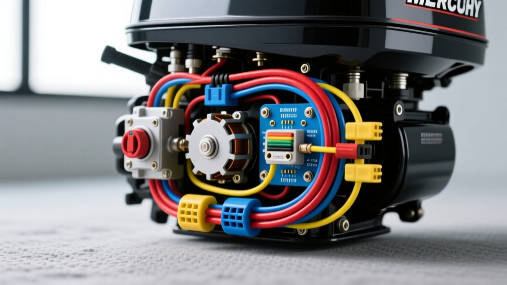
Technical Reference: 2 Stroke 50 HP Mercury Outboard Wiring Diagram
When diagnosing, rebuilding, or repowering the electrical system on a Mercury 50HP 2-stroke outboard (specifically the widely produced 1996-2005 2-cylinder blocks), relying on a generic automotive approach will lead to catastrophic failures and dangerous on-water situations. Marine environments demand strict adherence to SAE J378 Marine Cable Specifications and ABYC E-11 DC Electrical Standards. This technical specification reference breaks down the exact wire color codes, stator resistance values, ignition switch pinouts, and kill circuit logic required to properly map and troubleshoot the 2 stroke 50 hp Mercury outboard wiring diagram.
Core Electrical Architecture & Wire Gauge Requirements
The electrical system of the Mercury 50HP 2-stroke is divided into three primary circuits: the high-amperage starting/charging circuit, the low-amperage ignition/switchbox circuit, and the accessory/kill circuit. Unlike automotive applications, all wiring must utilize tinned, stranded copper wire (UL 1426 / SAE J378) to prevent black-wire corrosion, a phenomenon where saltwater wicks through the copper strands via capillary action, destroying the wire from the inside out.
Main Harness Sizing Standards
- Battery to Starter Solenoid: 4 AWG (or 2 AWG for runs exceeding 15 feet) to minimize voltage drop during the 120+ amp starter draw.
- Main Harness Feed (Key Switch to Engine): 10 AWG for the primary 12V+ feed to handle the fuel pump, ignition, and gauge loads.
- Signal and Trigger Wires: 14 AWG to 16 AWG. These low-current wires are highly susceptible to voltage drop; a mere 0.5V drop on a trigger signal can cause the switchbox to misfire at high RPMs.
Ignition Key Switch Pinout & Harness Mapping
The majority of 50HP Mercury 2-stroke models utilize a standard 5-terminal or 6-terminal ignition switch. Miswiring this switch is the most common cause of no-spark complaints and dead batteries. Below is the definitive pinout reference for the standard Mercury marine ignition switch.
| Terminal | Wire Color | Function | AWG Size |
|---|---|---|---|
| B (Battery) | Red/Purple | Main 12V+ Feed from Starter Solenoid/Battery | 10 AWG |
| C (Choke) | Yellow/Red | Activates Choke Solenoid (Richens fuel mixture for cold start) | 12 AWG |
| M (Magneto) | Black/Yellow | Kill Circuit (Grounds switchbox capacitors to stop engine) | 14 AWG |
| S (Start) | Yellow/Red | Engages Starter Solenoid Coil | 12 AWG |
| I (Ignition) | Purple | Provides 12V+ to engine harness and gauges in 'Run' position | 14 AWG |
Diagnostic Note: If the engine cranks but will not start, verify that the I (Purple) terminal is receiving a full 12V+ while the key is in the 'ON' position. If voltage drops below 10.5V, the switchbox will not fire the ignition coils. Furthermore, ensure the M (Black/Yellow) wire has infinite resistance to ground when the key is in the 'ON' position. Any continuity to ground here will instantly kill the spark.
Stator, Trigger, and Switchbox Diagnostics
The heart of the 2 stroke 50 hp Mercury outboard wiring diagram is the alternator stator and the CDI/switchbox. The stator generates raw AC voltage, which the switchbox rectifies and steps up to fire the ignition coils. Testing these components requires a Digital Voltmeter (DVM) and, crucially, a DVA (Direct Voltage Average) Adapter. Standard multimeters cannot accurately read the high-frequency, high-voltage pulses generated by the stator.
Stator Resistance and DVA Output Specifications
| Stator Wire Pairs | Resistance (Ohms) | DVA Output (Running) | Circuit Function |
|---|---|---|---|
| Yellow to Yellow | 0.35 - 0.70 Ω | 14 - 30V AC | Battery Charge (Feeds Rectifier) |
| Red to White | 110 - 140 Ω | 180 - 400V DVA | High-Speed Ignition Charge Coil |
| White to Brown (Trigger) | 1000 - 1300 Ω | N/A (AC Pulse) | Trigger Signal to Switchbox |
Real-World Failure Mode: A common failure on the 50HP 2-stroke is a shorted high-speed charge coil (Red to White). If your engine runs perfectly up to 3,000 RPM but completely bogs down or backfires above that threshold, the Red/White stator wire has likely broken down internally under heat. The resistance may test fine when cold, but a DVA test under load will reveal a voltage drop below 150V at high RPM, confirming a faulty stator.
The Kill Circuit and Stop Diode Logic
Understanding the kill circuit is mandatory for interpreting the Mercury 50HP wiring diagram. Unlike automotive engines that cut fuel or ground the ignition coil primary side, the Mercury 2-stroke stops by grounding the Black/Yellow wire. This wire connects directly to the switchbox capacitors. When grounded, the capacitors discharge into the engine block rather than firing the ignition coils.
Stop Diode and Safety Lanyard Integration
The Black/Yellow wire routes from the switchbox, through the main engine harness, to the ignition switch (Terminal M), and to the emergency safety lanyard switch. To prevent the ignition switch from back-feeding voltage into the kill circuit, Mercury utilizes a Stop Diode (typically located in the main harness or under the flywheel cover).
- Testing the Stop Diode: Set your multimeter to the diode test setting. Place the red lead on the engine side of the diode and the black lead on the harness side. You should read a voltage drop of 0.4V to 0.6V. Reversing the leads should read 'OL' (Open Line). If it reads 0.0V in both directions, the diode is shorted, and the engine will have no spark.
- Ghost Kill Circuit Faults: If you have disconnected the Black/Yellow wire at the switchbox and still have no spark, the fault is internal to the switchbox or the trigger. If spark returns when disconnected at the switchbox but dies when connected to the main harness, you have a chafed Black/Yellow wire shorting to the engine block inside the harness sleeve.
Starter Solenoid & High-Current Routing
The starter solenoid on the 50HP Mercury is a heavy-duty, marine-sealed relay designed to handle inrush currents exceeding 150 amps. The control circuit relies on the Yellow/Red wire from the ignition switch (Terminal S).
- Control Circuit Verification: When the key is turned to 'START', the Yellow/Red wire should deliver a minimum of 10.5V to the solenoid's small spade terminal. If voltage is present but the solenoid only clicks, the internal copper contacts are pitted and the solenoid must be replaced.
- Voltage Drop Testing: According to ABYC E-11 standards, the maximum allowable voltage drop on the positive starting circuit is 10% (1.2V on a 12V system). Connect your multimeter leads to the battery positive post and the starter motor positive terminal while cranking. A reading higher than 1.2V indicates corroded battery lugs, undersized wire (less than 4 AWG), or a failing solenoid.
Connector Integrity & Corrosion Prevention
The transition point between the boat harness and the engine harness is the Amphenol 14-pin connector. This is the most vulnerable point in the entire 2 stroke 50 hp Mercury outboard wiring diagram. Factory connectors are sealed, but years of vibration and UV exposure compromise the rubber gaskets.
When servicing this connector, never use standard automotive silicone grease, as it can degrade the plastic pins and trap moisture. You must use a marine-grade dielectric compound such as Molykote 111 or Mercury's proprietary Perfect Seal. Furthermore, any splices made during harness repair must be sealed using marine-grade adhesive-lined heat shrink (3M 471 series or equivalent). Standard vinyl electrical tape will unroll in a marine engine cowling within weeks due to the extreme heat cycles generated by the 2-stroke powerhead, leading to inevitable short circuits.
Final Diagnostic Verification
Always cross-reference your physical wire colors with the official Mercury Marine Service Manual for your specific serial number range, as mid-year production changes can occasionally alter trigger wire colors (e.g., swapping Brown/White for solid White). Properly mapping the stator, verifying the Black/Yellow kill circuit isolation, and ensuring ABYC-compliant wire gauges will guarantee a reliable, spark-rich ignition system capable of withstanding harsh marine environments.