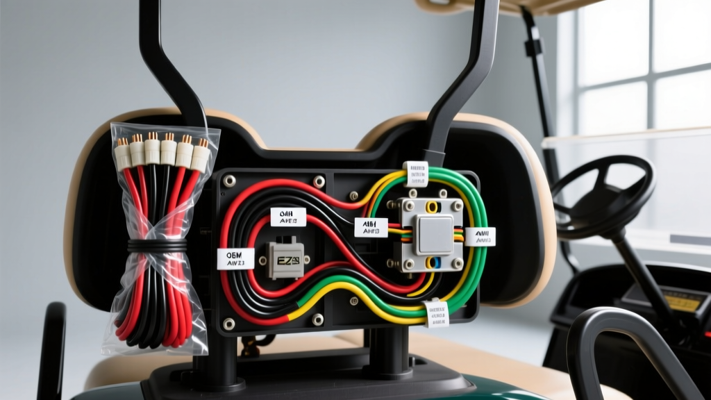
Decoding the EZGO Gas Wiring Diagram: Core Circuits
When restoring, troubleshooting, or upgrading an E-Z-GO gas-powered golf cart, having an accurate EZGO gas wiring diagram is the foundational step for any successful electrical project. Unlike their electric counterparts, which rely on complex 36V or 48V high-amperage motor controller networks, E-Z-GO gas models (such as the iconic TXT, Marathon, and ST Sport series) utilize a relatively straightforward 12-volt electrical system. This system is primarily tasked with managing the ignition sequence, the belt-driven starter/generator (ST/GEN), the voltage regulator, and auxiliary lighting circuits.
However, simplicity does not mean invulnerability. The harsh, high-vibration environment of a gas engine bay frequently leads to brittle insulation, corroded spade terminals, and voltage drops. When it is time to replace a degraded main harness or upgrade the ignition circuit, technicians and DIYers face a critical purchasing decision: should you invest in Original Equipment Manufacturer (OEM) harnesses, or opt for aftermarket universal kits? This product comparison and selection guide uses the factory EZGO gas wiring diagram as a baseline to evaluate the best wiring solutions, connector kits, and reference materials available on the market today.
Product Comparison: OEM vs. Aftermarket Main Harnesses
The main dash and engine harness is the central nervous system of your gas cart. Selecting the right replacement requires understanding how different manufacturers interpret the factory schematic.
1. OEM E-Z-GO Main Dash & Engine Harnesses
OEM harnesses are engineered to match the exact E-Z-GO factory specifications. When you consult an OEM EZGO gas wiring diagram, you will notice highly specific color codes—such as Black/White for the 12V ignition feed and Blue/White for the starter solenoid trigger wire. OEM harnesses utilize custom-molded Molex-style multi-pin connectors that plug directly into the factory dash switches and the ignition key cylinder without the need for splicing.
- Pros: Perfect plug-and-play fitment; exact wire color matching to factory service manuals; high-temperature automotive-grade loom; correct pin tension in connectors.
- Cons: Higher price point; longer lead times for older Marathon or early TXT models; limited availability for heavily modified custom builds.
2. Aftermarket Universal Gas Harness Kits
Aftermarket kits (from brands like 10L0L or Roykaw) are designed to be adaptable. Instead of matching E-Z-GO's proprietary color codes, these kits typically adhere to standard SAE J1128 primary wire standards, utilizing solid Red for 12V+ and solid Black for ground. While they include the necessary 14 AWG and 16 AWG wires, they often terminate in generic spade connectors or butt splices, requiring the installer to adapt the EZGO gas wiring diagram to the new generic color scheme.
- Pros: Highly affordable; readily available; excellent for custom rat-rod builds or carts with swapped engines; includes extra wire length for routing flexibility.
- Cons: Requires manual crimping and heat-shrinking; wire colors do not match factory diagrams; generic connectors may rattle loose under gas engine vibration.
Starter/Generator and Voltage Regulator Selection
The heart of the EZGO gas electrical system is the Starter/Generator and its corresponding Voltage Regulator (VR). When selecting replacement components or heavy-duty wiring kits for these circuits, the diagram dictates strict AWG requirements.
Heavy-Duty Solenoid and Cable Kits
The factory EZGO gas wiring diagram routes the main battery positive (B+) through a heavy-duty solenoid before reaching the starter/generator armature. Standard OEM kits use 4 AWG battery cables. However, for carts used in hilly terrain or those equipped with high-compression aftermarket engines, upgrading to a 2 AWG pure copper cable kit with a continuous-duty 12V solenoid is highly recommended. This reduces voltage drop during the high-amperage cranking phase (which can exceed 90 amps momentarily).
Voltage Regulator Harness Pigtails
The 4-pin voltage regulator on 1994+ TXT gas models is a notorious failure point, often taking the wiring pigtail down with it due to heat cycling. When buying a replacement VR, always select a kit that includes a new, pre-wired pigtail harness with sealed, weather-pack connectors. The factory diagram specifies: Red (Battery Sense/B+), Black (Chassis Ground), Yellow (Stator AC Input), and White/Green (Ignition/Field). Aftermarket pigtails that use standard spade connectors instead of sealed automotive connectors should be avoided, as moisture ingress will destroy the new regulator within a single season.
Reference Material Selection: Digital vs. Physical Diagrams
To effectively install any of the aforementioned products, you need the correct reference material. Here is how the top diagram formats compare for the professional or serious DIYer:
- OEM Laminated Dash Schematics: Best for quick reference in the garage. These 11x17 color-coded posters map the exact pinouts and are resistant to grease and water. Highly recommended for shops that service multiple TXT generations.
- Digital PDF Service Manuals: Best for deep-dive troubleshooting. Digital manuals allow you to zoom in on complex ground distribution nodes and trace the ignition kill circuit through the micro-switches on the forward/reverse shifter.
- Aftermarket Wire-Trace Apps: Interactive apps that allow you to tap a circuit on a digital EZGO gas wiring diagram to see real-world photos of the connector locations. Excellent for novices but often requires a monthly subscription.
Technical Specifications: E-Z-GO TXT Gas Ignition & Starter Circuit
Use the table below as a quick-reference cheat sheet when verifying your harness against the factory EZGO gas wiring diagram. All wire sizes conform to SAE J1128 GXL/TXL high-temperature standards, which are mandatory for engine-bay routing.
| Circuit Function | Factory Wire Color | AWG Rating | Connector Type | Torque Spec / Notes |
|---|---|---|---|---|
| Main Battery to Solenoid | Red (Solid) | 4 AWG (or 2 AWG) | 3/8" Ring Terminal | 9-11 ft-lbs (Apply dielectric grease) |
| Solenoid to ST/GEN (B+) | Red (Solid) | 4 AWG | 5/16" Ring Terminal | 8-10 ft-lbs |
| Ignition Switch to Coil | Black/White Stripe | 14 AWG | 1/4" Female Spade | Verify 12V+ in 'ON' position only |
| Solenoid Trigger (Microswitch) | Blue/White Stripe | 16 AWG | 5/16" Ring / Spade | Routes through F/R shifter microswitch |
| Voltage Regulator Ground | Black (Solid) | 12 AWG | 1/4" Ring Terminal | Critical: Must ground to clean engine block |
| ST/GEN Field (F) Post | Yellow/White | 12 AWG | 1/4" Ring Terminal | Do not overtighten; bakelite insulator is fragile |
Common Failure Modes & Expert Troubleshooting
Even with a perfect EZGO gas wiring diagram in hand, physical installation errors can mimic electrical component failures. As an automotive electrical expert, I frequently diagnose the following real-world issues after harness replacements:
The "Phantom Battery Drain" (Ignition Kill Circuit)
In E-Z-GO gas carts, the ignition coil is fired by grounding the negative side of the coil through the ignition switch and the F/R microswitches. If an aftermarket universal harness is installed and the installer mistakenly wires a constant 12V+ to the coil's negative terminal instead of a switched ground path, the cart will not fire, and the coil will overheat. Always use a multimeter to verify continuity to ground on the kill wire when the key is in the 'OFF' position.
Voltage Regulator Ground Starvation
The 4-pin VR relies on the Black wire to complete the circuit back to the battery negative. Many DIYers attach this ground to a painted engine bracket or a rusted exhaust heat shield. Because the engine is isolated from the chassis by heavy rubber motor mounts, the VR cannot find a path to ground. This results in the ST/GEN failing to charge the 12V battery, leading to a dead cart. The Fix: Always route the VR Black wire directly to the engine block or the main battery negative terminal, using a star washer to bite through any corrosion or paint.
Connector Fretting Corrosion
Gas engines produce high-frequency vibrations that cause standard brass spade connectors to loosen and arc, melting the plastic housing. When selecting a wiring kit, prioritize products that use nylon-insulated, locking spade terminals or apply a dab of SAE-compliant dielectric grease to every connection in the engine bay. This single step will double the lifespan of your aftermarket harness and keep your cart running flawlessly on the fairway.