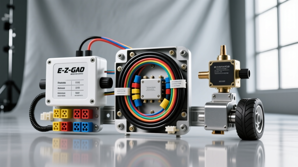
Diagnosing and Upgrading Components to Solve Drivetrain Failures
When troubleshooting problems with electric golf carts, the root cause almost always traces back to the high-current drivetrain or the low-voltage logic circuits. Symptoms like sudden power loss, jerky acceleration, melted battery terminals, or a clicking solenoid are rarely isolated incidents; they are cascading failures caused by undersized wiring, degraded contacts, or mismatched controller profiles. As an automotive electrical specialist, I recommend approaching these repairs not just as part replacements, but as system upgrades. Selecting the correct Motor Speed Controller (MSC), heavy-duty solenoid, and properly gauged interconnect cables is critical for long-term reliability.
This product comparison and selection guide breaks down the most effective replacement components for E-Z-GO TXT/RXV, Club Car DS/Precedent, and Yamaha Drive models, providing exact pinouts, AWG requirements, and torque specifications to ensure your repair outlasts the OEM configuration.
Motor Speed Controller (MSC) Selection: Curtis vs. Alltrax
The MSC is the brain of the golf cart. When carts experience 'limp mode' errors, thermal shutdowns, or erratic speed curves, the controller is often failing due to undersized MOSFETs or degraded internal capacitors. When selecting a replacement, you must match the motor type (Series, Shunt, or Sepex) and the throttle input type (ITS or MCRO).
Comparing Top Replacement Controllers
| Feature | Curtis 1205 (Series) | Curtis 1206 (Sepex) | Alltrax DCX 540 |
|---|---|---|---|
| Peak Current | 325A (2 min) | 350A (2 min) | 540A (2 min) |
| Continuous Current | 85A | 90A | 130A |
| PWM Frequency | 16 kHz | 16 kHz | 18 kHz (Adjustable) |
| Motor Type | Series Wound | Separately Excited | Series / Shunt |
| Throttle Input | 0-5V / 0-10k Ohm | 0-5V / 0-10k Ohm | 0-5V / 0-10k Ohm |
| Connector Type | 13-Pin Molex | 13-Pin Molex | 14-Pin Molex |
Source: Curtis Instruments Motor Speed Controllers
Controller Wiring Harness Pinout (Standard 13-Pin Molex)
Incorrect pin mapping is a leading cause of instant controller failure upon key-up. When wiring a new Curtis 1205 or 1206, adhere strictly to this standard pinout configuration:
- Pin 1 (B+): Main battery positive (Heavy Red, 2 AWG).
- Pin 2 (Key): Key switch input (Blue, 16 AWG).
- Pin 5 (Throttle Hi): Throttle signal max (Yellow, 18 AWG).
- Pin 6 (Throttle Lo): Throttle signal min (Green, 18 AWG).
- Pin 7 (Forward): F/R switch forward input (Orange, 16 AWG).
- Pin 8 (Reverse): F/R switch reverse input (White, 16 AWG).
- Pin 13 (Fault): LED diagnostic output.
Expert Tip: Always apply dielectric grease (like Amphenol PT2) to the Molex connector pins before mating. Moisture intrusion in the logic harness is a primary cause of ghost-throttle problems and HPD (High Pedal Disable) lockouts.
High-Current Solenoid and Main Cable Upgrades
A rapid clicking sound from the solenoid, or a cart that dies under heavy load (like climbing a hill), indicates severe voltage drop across the main contacts or the high-current cables. OEM solenoids are often rated for only 85A continuous, which is insufficient for upgraded motors or frequent towing.
Solenoid Selection: Albright vs. Trombetta
For high-torque applications, upgrade to an Albright SW200-48V or a Trombetta 48V Heavy-Duty solenoid. The Albright SW200 features silver-cadmium oxide contacts that resist arcing and welding, rated for 200A continuous and up to 800A peak.
Solenoid Coil Diagnostics and Wiring
Before replacing a solenoid, verify the coil activation circuit. A 48V coil should measure between 38 and 45 ohms across the small terminals. If the resistance is infinite, the coil is open. If it reads near zero, the coil is shorted.
- Activation Current: ~1.2 Amps.
- Hold Current: ~0.4 Amps (via internal economizer circuit).
- Pre-charge Resistor: Always install a 250-ohm, 10W pre-charge resistor between the main B+ and Motor+ terminals. This prevents contact welding by equalizing voltage across the capacitor bank before the main contacts close.
Main Cable Sizing and Torque Specifications
Never use standard stranded automotive wire for the main battery and motor runs. You must use 2 AWG fine-strand welding cable (meeting SAE J1128 standards for flexibility and heat dissipation). Copper lugs must be hydraulically crimped, not hammered.
Torque Specs for 1/4"-20 Solenoid Studs:
- Target Torque: 75 to 85 in-lbs (6.2 to 7.0 ft-lbs).
- Warning: Over-torquing to 100+ in-lbs will crack the internal bakelite bus bar, causing internal arcing and catastrophic solenoid failure.
Forward/Reverse (F/R) Switch and Micro-Switch Failures
One of the most dangerous problems with electric golf carts is the cart taking off unexpectedly or failing to change direction. This is usually traced to the F/R switch assembly. In older Club Car DS models with the V-Glide, the micro-switches are prone to arcing, melting the plastic housing, and fusing the contacts. Modern IQ and Precedent models use a rotary FNR switch, which is more robust but still susceptible to moisture-induced logic faults.
Upgrading the Logic Switches
If your cart uses external micro-switches on the F/R shaft, replace the OEM 10A switches with heavy-duty 25A rated micro-switches featuring gold-plated contacts.
Club Car IQ FNR Switch Pinout (10-Pin Connector):
- Pin 1: Forward Logic (Green/White Stripe)
- Pin 2: Reverse Logic (White/Black Stripe)
- Pin 3: 15V Logic Supply from OBC/Controller
- Pin 4: Tow/Run Switch Input
When diagnosing F/R issues, use a multimeter to check for a clean 48V (or 15V logic, depending on the controller) signal at the controller harness while toggling the lever. A voltage reading that fluctuates between 2V and 10V indicates severe internal switch pitting.
Battery Pack Interconnects and Voltage Drop Diagnostics
A 48V golf cart battery pack consists of either six 8V batteries or four 12V batteries. The interconnect cables carry the full amperage of the motor. OEM interconnects are often 4 AWG or 6 AWG, which creates a bottleneck, leading to localized heating, terminal sulfation, and premature battery death.
Interconnect Cable Selection Chart
| System Voltage | Motor Peak Draw | Recommended Interconnect AWG | Max Allowable Voltage Drop |
|---|---|---|---|
| 36V (6x 6V) | 250A | 2/0 AWG Ultra-Flex | 0.2V per cable |
| 48V (6x 8V) | 300A | 2/0 AWG Ultra-Flex | 0.15V per cable |
| 48V (4x 12V) | 350A | 4/0 AWG Ultra-Flex | 0.10V per cable |
Reference: Albright International High-Current Specifications
When installing new 2/0 AWG interconnects, clean the battery posts with a brass wire brush and apply a thin layer of No-Ox-Id 'A-Special' conductive grease. This prevents galvanic corrosion between the lead post and the copper lug, ensuring a micro-ohm level connection.
Throttle Input Devices: ITS vs. MCRO
Jerky acceleration or 'dead spots' in the pedal travel are common problems with electric golf carts related to the throttle sensor. You must identify whether your cart uses an Inductive Throttle Sensor (ITS) or a Micro-switch Controlled Resistor (MCRO) before ordering parts.
ITS (Inductive Throttle Sensor) Diagnostics
Used in most modern E-Z-GO RXV and Club Car Precedent models, the ITS uses a Hall-effect sensor with no moving wiper parts. It requires three wires:
- Red: 5V Reference from Controller.
- Black: Sensor Ground.
- White/Signal: Output voltage (Typically 0.8V at rest, ramping to 4.2V at full throttle).
If the signal wire reads 5V constantly, the internal magnet has detached from the pedal box shaft. If it reads 0V, the 5V reference trace on the controller logic board has likely burned out.
MCRO (Potentiometer) Calibration
Older E-Z-GO TXT models use an MCRO. This relies on a physical wiper moving across a carbon track. When replacing an MCRO, you must calibrate the 'zero' point. Connect a multimeter to the wiper and ground pins. Adjust the physical mounting bracket until the resting voltage reads exactly 0.8V to 1.0V. Setting it too high (above 1.2V) will trigger the controller's High Pedal Disable (HPD) safety feature, preventing the cart from moving until the key is cycled.
Summary of Best Practices
Solving persistent problems with electric golf carts requires moving beyond cheap, direct-fit OEM replacements. By upgrading to an Alltrax or high-amperage Curtis controller, installing an Albright heavy-duty solenoid, and rewiring the main battery bank with 2/0 AWG SAE J1128 compliant welding cable, you eliminate the thermal bottlenecks that cause 90% of all electrical drivetrain failures. Always verify pinouts with a wiring diagram specific to your exact model year, and use a digital torque wrench on all high-current terminal connections.