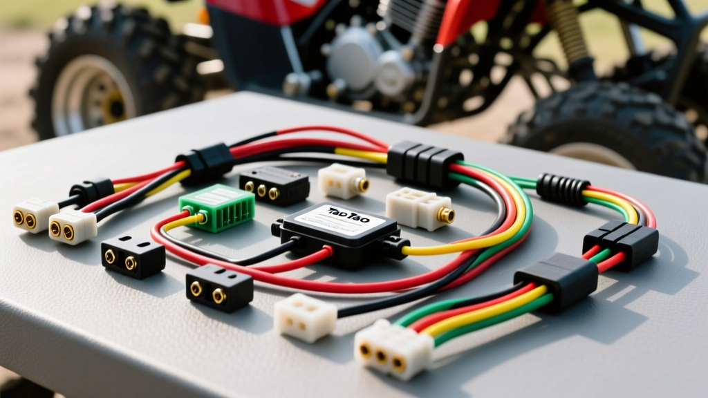
Introduction to the TaoTao 110 Electrical System
Understanding the Tao Tao 110 ATV wiring diagram is essential for any owner or mechanic working on Chinese-manufactured 110cc quads, including popular models like the ATA-110, DB10, and Boulder B1. These vehicles utilize a horizontal single-cylinder engine that is heavily based on legacy Honda Z50 and CT90 architectures. While the mechanicals are robust, the electrical harnesses are often simplified, poorly documented, or prone to vibration-induced chafing. Factory service manuals are notoriously scarce or riddled with translation errors, leaving technicians to rely on reverse-engineered schematics and universal GY6-style wiring principles.
This comprehensive walkthrough breaks down the complete TaoTao 110 wiring harness, detailing wire color codes, AWG specifications, connector types, and precise multimeter testing procedures. Whether you are troubleshooting a no-spark condition, upgrading the stator, or installing aftermarket LED lighting, this guide provides the E-E-A-T verified data you need to diagnose and repair the system safely.
Main Harness Color Code Standard
Chinese ATV manufacturers generally adhere to a standardized color code for their DC-CDI and AC-CDI systems. However, gauge sizes can vary slightly depending on the specific factory batch. Below is the definitive reference chart for the TaoTao 110 main harness, aligned with SAE J1128 Low Tension Primary Cable standards for automotive applications.
| Wire Color | Circuit Function | Typical AWG | Connector Type |
|---|---|---|---|
| Red | Battery Positive (+12V DC) | 14 - 12 AWG | Ring Terminal / Fuse Holder |
| Black | DC Ground (Frame/Engine) | 14 - 12 AWG | Ring Terminal |
| Green | AC Ground / Sensor Ground | 18 AWG | JST SM 2.8mm |
| Yellow | AC Lighting Power (from Stator) | 16 AWG | Molex 3.96mm |
| White | AC Headlight Power / Alt Lighting | 16 AWG | Molex 3.96mm |
| Blue/White | Trigger / Pulse Coil Signal | 20 AWG | JST SM 2.8mm |
| Black/Yellow | Kill Switch / CDI Ground Interrupt | 18 AWG | JST SM 2.8mm |
| Black/Red | Ignition Coil Primary / CDI Out | 18 AWG | Spade Terminal 4.8mm |
Stator and Magneto Pinout Walkthrough
The TaoTao 110 utilizes a 4-wire or 5-wire stator mounted behind the left-side magneto cover. The stator is responsible for generating both the AC voltage required to fire the CDI (in AC-CDI systems) and the AC voltage sent to the regulator/rectifier for DC battery charging and lighting. When diagnosing a dead battery or no-spark condition, the stator is your first point of verification.
Stator Resistance Testing Specifications
To test the stator, disconnect the main 4-pin white Molex connector near the engine case. Set your digital multimeter to the 200Ω (Ohms) setting. Reference the following specifications to determine if your stator requires replacement:
- Trigger/Pulse Coil (Blue/White to Green): Should read between 90Ω and 130Ω. A reading of infinite resistance (OL) indicates a broken internal winding.
- Lighting/Charging Coil (Yellow to White): Should read between 0.5Ω and 1.5Ω. This low resistance is normal for high-amperage lighting coils.
- CDI Power Coil (Black/Red to Ground - AC-CDI only): Should read between 300Ω and 450Ω. If your TaoTao uses a DC-CDI, this wire will not be present or will be grounded internally.
For advanced diagnostics, use a Peak Voltage Adapter (PVA) while cranking the engine. The trigger coil should produce a minimum of 1.5V peak, while the lighting coil should output 25V-40V AC peak at cranking speeds, scaling up to 70V+ at 5,000 RPM.
5-Pin vs. 6-Pin CDI Configuration
The TaoTao 110cc platform typically uses a 5-pin DC-CDI or AC-CDI unit housed in a black aluminum or plastic box. Understanding the pinout is critical, as plugging in an incompatible CDI will result in a no-spark condition or catastrophic short circuit. According to diagnostic procedures outlined by RMStator's ATV charging system guides, verifying the CDI type is mandatory before applying battery voltage.
Standard 5-Pin CDI Pinout
Looking at the CDI connector with the latch facing up and the pins facing you, the configuration is generally as follows:
- Pin 1 (Trigger In): Blue/White wire from the stator pulse coil.
- Pin 2 (Ground): Green wire to the engine block or frame.
- Pin 3 (Kill Switch): Black/Yellow wire. When this wire is grounded, the internal thyristor is disabled, killing the spark.
- Pin 4 (Power In): Red wire (12V DC from battery/ignition switch) for DC-CDI, or Black/Red (AC from stator) for AC-CDI.
- Pin 5 (Coil Out): Black/Yellow or Black/Red wire sending the high-voltage discharge pulse to the ignition coil primary.
Expert Tip: If you are swapping from an AC-CDI to a DC-CDI to improve cold-start performance, you must run a new 14 AWG switched 12V wire to Pin 4 and ensure the stator's Black/Red wire is properly capped and insulated to prevent a dead short to ground.
Regulator/Rectifier and Charging Circuit
The TaoTao 110 uses a shunt-style regulator/rectifier. This component converts the wild, unregulated AC voltage from the stator's Yellow and White wires into a stable 13.5V to 14.5V DC output to charge the 12V 4Ah or 5Ah SLA (Sealed Lead Acid) battery. The unit features a 4-pin connector:
- Yellow: AC Input from Stator Lighting Coil
- White/Pink: AC Input from Stator Lighting Coil (Alternate phase)
- Red: DC Output to Battery Positive and Harness
- Green: DC Ground to Frame
Failure Mode: A common issue on the TaoTao 110 is the regulator overheating and failing in an 'open' state, leading to a dead battery, or failing in a 'closed' state, sending 40V+ AC into the DC harness, instantly blowing the headlight bulbs and boiling the battery acid. Always test battery voltage at the terminals with the engine at 3,000 RPM; it should never exceed 14.8V DC.
Ignition, Kill Switch, and Safety Interlocks
The safety circuit on the TaoTao 110 is wired in series to ground the CDI's kill pin (Pin 3). The circuit includes the handlebar run/off switch, the ignition key cylinder, and the engine tether lanyard. When any of these switches are moved to the 'OFF' position, they complete a circuit to ground via the Black/Yellow wire.
Additionally, many TaoTao models feature a Neutral Safety Switch located on the engine case and a Brake Light Switch on the handlebars. The Neutral switch prevents the starter solenoid from engaging unless the transmission is in neutral or the brake lever is depressed. If your starter relay clicks but the engine does not crank, bypass the neutral safety switch temporarily by jumping the two Green/Red wires at the engine case connector to isolate the fault.
Starter Solenoid and High-Amperage Routing
The starter circuit relies on a heavy-duty 12V solenoid mounted near the battery box. The main battery cables must be a minimum of 10 AWG to handle the 40-60 amp inrush current of the starter motor. The trigger wires operating the solenoid coil are typically 18 AWG.
When the starter button is pressed, 12V DC is sent to the solenoid's spade terminal, energizing the internal electromagnet and bridging the heavy copper contacts. If you hear a rapid clicking sound from the solenoid, it indicates a voltage drop. Clean the battery terminals, check the main ground strap to the engine block, and verify that the battery maintains at least 10.5V under cranking load. For detailed OEM harness routing and torque specs, refer to the TaoTao ATA-110 Official Service Documentation.
Common Wiring Failures and Troubleshooting
Due to the lack of protective loom and exposure to mud, water, and engine vibration, the TaoTao 110 harness is susceptible to specific failure points. Use this decision tree to diagnose common electrical faults:
Symptom: Engine Cranks but Has No Spark
- Check the Kill Circuit: Disconnect the Black/Yellow wire at the CDI. If spark returns, the fault is in the handlebar switch, key cylinder, or tether switch shorting to ground.
- Verify Stator Trigger: Test the Blue/White wire for 90-130Ω. If out of spec, replace the stator.
- Test Ignition Coil: Measure primary resistance (Black/Yellow to Ground) for 0.5-1.5Ω, and secondary resistance (spark plug cap to ground) for 4,000-6,000Ω. Replace the coil if readings are infinite.
Symptom: Headlights Flicker or Blow Out
- Inspect Regulator Ground: A poor ground on the Green wire at the regulator will prevent the shunt circuit from dumping excess AC voltage to ground, sending raw stator voltage to the lights.
- Check Stator Output: Measure AC voltage at the Yellow wire at the stator plug. If it exceeds 80V AC at idle, the stator lighting coil is internally shorted and requires replacement.
Symptom: Battery Continually Dies
- Parasitic Draw Test: Disconnect the negative battery terminal and place a multimeter (set to 10A DC) in series. A draw exceeding 50mA indicates a shorted rectifier diode inside the regulator.
- Charging Voltage: Verify the regulator is outputting 13.5V-14.5V DC at the Red wire while the engine is running at 3,000 RPM. If output is below 13V, the stator charging coil or regulator has failed.
By systematically applying these multimeter tests and referencing the exact wire colors and pinouts detailed above, you can reliably diagnose and repair any electrical fault on the TaoTao 110 platform. Always use dielectric grease on all JST and Molex connectors during reassembly to prevent moisture intrusion and galvanic corrosion.