Introduction to the RZR Electrical Architecture
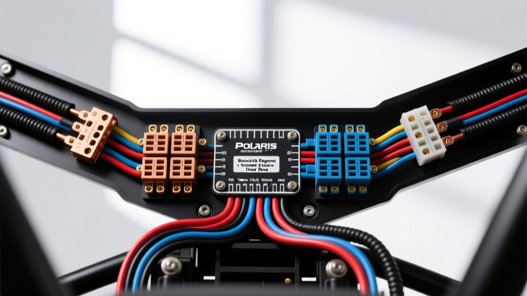
When modifying a Polaris RZR for off-road expeditions, understanding the factory electrical distribution system is critical. The RZR busbar wiring diagram represents the central nervous system for accessory integration, routing power from the battery and stator to high-draw components like light bars, winches, and communication systems. However, as UTVs have evolved from simple utility vehicles to high-performance machines like the RZR Pro R and Turbo S, the electrical architecture has shifted from basic mechanical terminal strips to complex Power Distribution Modules (PDMs).
This advanced technical deep dive dissects the factory Polaris RZR busbar layouts, details the exact wire color codes and AWG specifications, and provides a comprehensive engineering guide to upgrading your terminal blocks to handle extreme amperage loads without inducing voltage drop or thermal runaway.
Decoding the Factory RZR Busbar Wiring Diagram
On most Polaris RZR XP 1000 and Turbo models (2016-present), the primary accessory busbar is located under the hood, near the firewall or integrated directly into the PDM enclosure. This terminal block serves as the main junction for aftermarket accessories. To properly utilize the RZR busbar wiring diagram, you must understand the specific pinout and terminal designations.
Terminal Block Pinout and Wire Color Codes
The factory accessory terminal block typically features four to six M6 threaded studs. Understanding the factory wire color codes is essential for tracing circuits back to the PDM or ignition switch.
- Red/White Stripe: Switched 12V+ (Key-on/Run position). This circuit is protected by a 20A or 30A fuse in the PDM and is designed for low-draw accessories like LED rock lights or relay triggers.
- Solid Red: Constant 12V+ (Battery direct). Used for memory circuits or accessories that require power when the ignition is off (e.g., winch solenoids, coolers).
- Black/Yellow Stripe: Chassis Ground. Tied to the main negative battery terminal via the engine block and frame grounding straps.
- Orange: Accessory delay circuit (maintains power for 10-15 seconds after key-off on select Pro R models).
Factory Busbar Terminal Specifications
| Terminal Parameter | Factory Specification | Upgrade Recommendation |
|---|---|---|
| Stud Thread Size | M6 x 1.0 Pitch | 5/16'-18 or 3/8'-16 (Marine Grade) |
| Max Continuous Amperage | 20A per post (30A peak) | 150A+ per post (Copper Busbar) |
| Base Material | Tin-plated Brass / Zinc | Electroplated Copper (CDA 110) |
| Nut Torque Spec | 4.0 - 4.5 Nm (35-40 in-lbs) | 5.5 Nm (48 in-lbs) with Belleville washers |
| Recommended Wire Gauge | 12 AWG to 10 AWG | 8 AWG to 4 AWG for main feeds |
The Bottleneck: Why Factory Busbars Fail Under Load
A common failure point in heavily modified RZRs is the melting of the factory plastic busbar housing. This is rarely a defect in the Polaris design; rather, it is a result of operators exceeding the engineered amperage limits of the terminal block. According to SAE J1128 standards for low-tension primary cable, electrical resistance generates heat proportional to the square of the current (I²R). When you connect a 40A LED light bar directly to a factory 20A-rated switched busbar post, the brass terminal acts as a resistor.
Voltage Drop and Thermal Runaway Calculations
To calculate the voltage drop across your busbar connections, use the standard automotive DC formula:
VD = (2 × K × I × L) / CM
- K = Specific resistance of copper (12.9 ohms per mil-foot at 75°C)
- I = Current draw in Amps
- L = One-way wire length in feet
- CM = Circular mils of the wire (e.g., 10 AWG = 10,380 CM, 4 AWG = 41,740 CM)
If you are drawing 25A through a 10 AWG wire that is 12 feet long from the battery to the busbar, and another 6 feet from the busbar to the accessory, your total length (L) is 18 feet. The voltage drop will be approximately 1.34V. While this seems acceptable, the physical bottleneck at the M6 brass terminal creates a localized micro-voltage drop, generating intense heat that softens the surrounding nylon/plastic housing, leading to terminal pull-out and short circuits.
Advanced Upgrade: Installing an Auxiliary Copper Busbar System
For high-amperage applications (winches, high-output alternators, multiple 50-inch light bars), you must bypass the factory accessory block for heavy loads and install an auxiliary marine-grade copper busbar. This aligns with Blue Sea Systems' 12V distribution best practices for harsh, high-vibration environments.
Step-by-Step High-Amperage Integration
- Mounting the Auxiliary Busbar: Install a CDA 110 copper busbar with polycarbonate insulation covers on the passenger-side firewall or directly above the PDM. Use M6 rivet nuts (Rivnuts) for secure mounting to the RZR's roll cage or firewall sheet metal.
- Main Power Feed Routing: Run a 2 AWG or 4 AWG primary wire directly from the positive battery terminal to the new busbar. Do NOT route this through the factory PDM.
- Overcurrent Protection: Install an MRBF (Marine Battery Fuse) or Class T fuse within 7 inches of the battery positive terminal. For a 150A busbar, use a 150A Class T fuse to protect the main 4 AWG feed wire.
- Grounding Architecture: Install a matching negative copper busbar. Run a 2 AWG ground cable from the negative battery terminal to this busbar. From here, route 8 AWG or 10 AWG ground wires to your accessories. This eliminates reliance on the RZR's tubular steel frame, which suffers from poor conductivity due to powder coating and pivot-point resistance.
- Terminal Crimping: Use closed-barrel, adhesive-lined heat shrink ring terminals. Crimp with a hex-indent crimper to ensure a gas-tight connection that prevents moisture ingress and galvanic corrosion.
Relay Logic and Accessory Switch Panel Integration
The correct way to use the factory RZR busbar wiring diagram when installing an auxiliary system is to use the factory block strictly for trigger signals. By utilizing the factory switched 12V+ (Red/White) wire to trigger the 86-pin of a Bosch-style 5-pin relay, you draw less than 0.2 Amps from the factory PDM. The heavy current (Pin 30 to Pin 87) is then sourced directly from your new auxiliary copper busbar.
Bosch Relay Pin Configuration Reference
- Pin 30: 12V+ Constant (from Auxiliary Busbar via inline blade fuse)
- Pin 85: Ground (to Auxiliary Negative Busbar)
- Pin 86: Trigger 12V+ (from Factory RZR Switched Busbar Post)
- Pin 87: Output to Accessory (e.g., Light Bar positive)
- Pin 87a: Normally Closed (Unused in standard accessory wiring)
Expert Troubleshooting: Ground Faults and Parasitic Draws
When modifying the RZR electrical system, issues frequently arise that mimic a bad stator or failing PDM. Use this decision tree to isolate busbar and wiring faults.
Symptom: Accessory Flickers or Dims Over Bumps
- Cause 1: Loose M6 terminal nut on the busbar.
Fix: Torque all busbar nuts to 4.5 Nm. Apply a drop of medium-strength thread locker (Loctite 243) to prevent vibration-induced backing off. - Cause 2: Frame ground reliance.
Fix: Run a dedicated 10 AWG ground wire from the accessory directly to the negative busbar or engine block. The RZR frame is not a reliable ground conductor for high-draw items.
Symptom: PDM Throws a Fault Code / Accessory Shuts Off
- Cause: Exceeding the factory busbar amperage limit, causing the PDM's solid-state resettable breaker to trip.
Fix: Move the accessory's power feed to the auxiliary copper busbar and use the factory busbar only for a relay trigger.
Symptom: Parasitic Battery Drain Overnight
- Cause: Wiring an accessory to the constant 12V+ (Solid Red) busbar post without an inline mechanical switch or isolation relay.
Fix: Verify wiring against the RZR busbar wiring diagram. Ensure all constant-power accessories (like winch solenoids or amplifiers) have a physical in-cab kill switch or are wired through a relay triggered by a switched circuit.
Conclusion
Mastering the RZR busbar wiring diagram is about recognizing the limits of factory components and engineering a robust, high-amperage secondary system. By respecting AWG sizing, utilizing proper copper busbars, and isolating heavy loads from the sensitive Polaris PDM, you ensure your UTV's electrical system remains reliable in the most extreme off-road conditions. Always refer to Littelfuse's automotive application guides when selecting fuses and busbar hardware to guarantee your modifications meet rigorous safety standards.