Transitioning to Next Level Auto Electric Fundamentals
Every automotive enthusiast starts by swapping fuses, replacing batteries, and perhaps installing a basic stereo. However, moving into the realm of next level auto electric work requires a fundamental shift in how you view vehicle architecture. It is no longer about simply making a connection; it is about managing electron flow, mitigating voltage drop, and utilizing OEM-grade termination methods. Beginners rely on twist-and-tape splices and undersized wires, hoping the circuit holds. Advanced technicians rely on physics, SAE standards, and sealed connector systems to ensure longevity in high-vibration, high-heat engine bay environments.
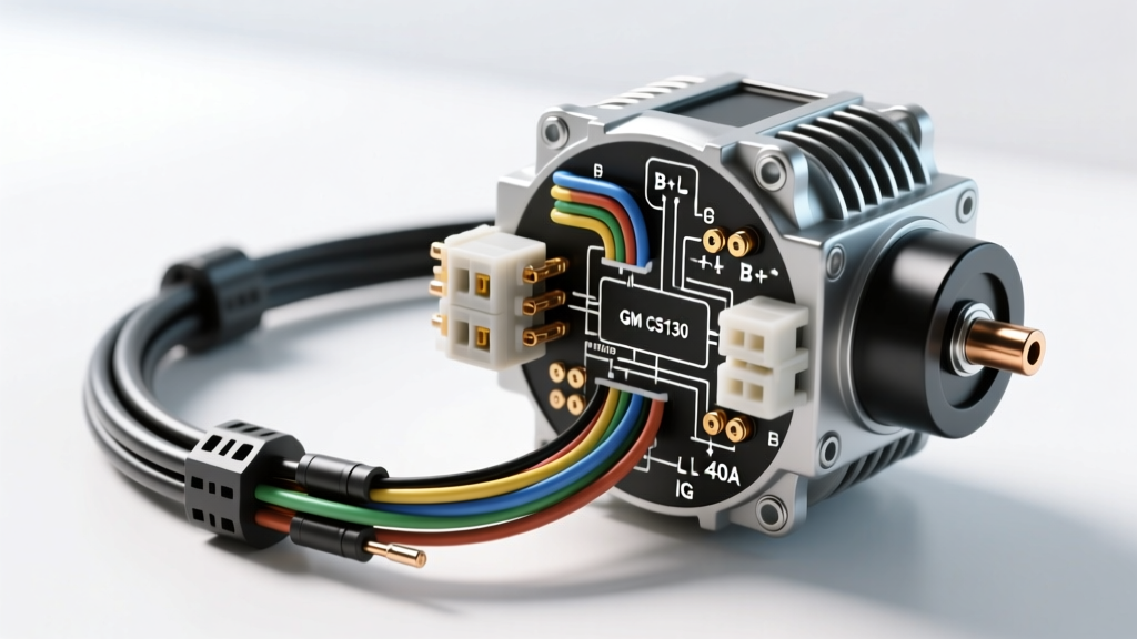
This guide bridges the gap between novice repairs and professional-grade circuit design. We will cover the critical mathematics of wire sizing, the proper construction of a high-amperage relay harness, and the precise wiring requirements for upgrading a classic GM 1-wire alternator to a modern, 3-wire GM CS130 system. By mastering these concepts, you will eliminate parasitic drains, prevent voltage-induced ECU faults, and build electrical systems capable of handling modern high-draw accessories.
The Math Behind the Magic: Voltage Drop and SAE J1128
The most common failure point in amateur automotive wiring is ignoring voltage drop over distance. A wire gauge that can safely handle 30 amps over a 2-foot span will suffer severe voltage drop and potential overheating over a 15-foot run from the battery to a rear-mounted auxiliary fuel pump. According to SAE J1128 standards for low-tension primary cable, wire sizing must account for the total circuit length (positive and negative paths combined) and the acceptable voltage drop (typically no more than 0.5V for a 12V system).
When selecting wire, always use automotive-grade cross-linked polyethylene (XLPE) insulation, such as TXL or GXL. These thin-wall wires withstand engine bay temperatures up to 125°C (257°F) and resist abrasion far better than standard PVC wire found in hardware stores.
AWG Sizing and Amperage Reference Chart
| AWG Size | Max Continuous Amps | Resistance (Ohms/1000ft) | Common Application |
|---|---|---|---|
| 18 AWG | 6A | 6.38 | Sensors, ECU signals, dash illumination |
| 14 AWG | 15A | 2.52 | Relay coils, horn circuits, tail lights |
| 10 AWG | 30A | 0.99 | Relay power feeds, electric fans, fuel pumps |
| 8 AWG | 45A | 0.62 | High-amperage lighting, winch solenoid feeds |
| 4 AWG | 130A | 0.24 | Alternator main output, battery relocation |
Moving Beyond Splices: Terminal Crimping and Sealed Connectors
To achieve true next level auto electric reliability, you must abandon twist connectors, solder-only joints, and electrical tape. Solder creates a rigid point in a flexible wire, which eventually fatigues and breaks under engine vibration. Furthermore, solder wicks moisture through capillary action, leading to green corrosion inside the insulation.
The industry standard is a mechanical crimp using open-barrel terminals or stamped-and-formed terminals inside sealed housings. For engine bay applications, the TE Connectivity Deutsch DT Series and Delphi Weather-Pack are the gold standards. When building a Weather-Pack connection, the silicone seals must be slid onto the wire before crimping the terminal. The crimp tool (such as an IWISS IWS-1424A) must crush both the wire grip and the insulation grip simultaneously. Finally, the terminal is inserted into the nylon housing until the tang clicks, and the secondary wedge lock is engaged to prevent the terminal from backing out.
Practical Application: Building a 40A Next-Level Relay Harness
Running high-draw accessories like off-road LED light bars or dual cooling fans directly through a dashboard switch is a recipe for melted switch housings and fires. A proper relay harness uses a low-amperage switch to control a high-amperage electromagnetic coil. We will use a standard ISO mini relay (Bosch-style SPDT) to control a 25A LED light bar.
ISO Mini Relay Pinout and Wiring Guide
| Relay Pin | Function | Wire Gauge & Color | Connection Destination |
|---|---|---|---|
| Pin 30 | Common (Power In) | 10 AWG Red | Direct to Battery (+) via 30A inline MAXI fuse |
| Pin 87 | Normally Open (Power Out) | 10 AWG Red | Positive input of the LED Light Bar |
| Pin 85 | Coil Ground | 14 AWG Black | Chassis ground (ring terminal to bare metal) |
| Pin 86 | Coil Switched Power | 14 AWG Blue | Output side of the dashboard toggle switch |
The Flyback Diode: A Pro-Level Addition
When the relay coil (an inductor) is de-energized, the collapsing magnetic field generates a high-voltage reverse spike (inductive kickback). This spike can damage solid-state switches, ECU drivers, or sensitive CAN-bus modules. To prevent this, solder a 1N4001 rectifier diode across pins 85 and 86. The silver stripe on the diode must face Pin 86 (the switched positive side). This provides a safe path for the reverse voltage to dissipate within the coil loop, protecting your vehicle's delicate electronics.
Upgrading the Heartbeat: GM CS130 3-Wire Alternator Wiring
One of the most common upgrades in classic GM trucks and muscle cars is replacing the aging 1-wire Delco 10SI alternator with a modern, internally regulated GM CS130. The 1-wire alternator is notorious for requiring high RPMs to 'excite' the field and begin charging, and it cannot sense voltage drops at the battery. The CS130 solves this with a 4-pin connector (though typically only 3 pins are utilized in custom swaps), allowing for precise voltage regulation and dashboard integration.
According to the Bosch Automotive Handbook principles of voltage regulation, the alternator must measure the voltage exactly where the load is consumed. The CS130 achieves this via a dedicated sense wire.
CS130 Alternator 4-Pin Connector (Delphi 12052844) Pinout
| Terminal / Pin | Function | Wire Spec | Routing & Critical Notes |
|---|---|---|---|
| L (Pin D) | Lamp / Indicator | 18 AWG Brown/White | Connects to the dashboard 'GEN' or 'ALT' warning light. Provides initial excitation current to the rotor. |
| S (Pin B) | Battery Sense | 12 AWG Red | CRITICAL: Must route directly to the battery positive post or main fuse block positive bus. Requires a 10A inline AGC fuse. |
| F (Pin A) | Field / Ignition | 14 AWG Pink | Connects to a switched 12V ignition source. Turns the internal regulator on and off with the key. |
| P (Pin C) | Phase / Stator | N/A (Unused) | Stator tap used for tachometer signals in some marine applications. Leave disconnected and sealed in standard auto swaps. |
Real-World Failure Mode: The Sense Wire Mistake
The most frequent error made by beginners when wiring a CS130 is routing the 'S' (Sense) wire directly to the alternator's main output post (BATT terminal) instead of routing it back to the battery. If you do this, the regulator reads the 14.2V being produced at the alternator case and shuts down the charging cycle. However, due to voltage drop across 15 feet of aging engine bay wiring, the actual voltage reaching the battery may only be 12.6V. The result is a chronically undercharged battery and eventual stranded vehicle. Always route the sense wire independent of the main charge cable, directly to the battery positive terminal.
Conclusion: Building for the Long Haul
Mastering next level auto electric fundamentals means respecting the environment in which your vehicle operates. Engine bays are hostile territories filled with 250°F exhaust heat, corrosive road salts, and high-frequency vibrations. By calculating voltage drop using SAE standards, utilizing sealed Weather-Pack and Deutsch connectors, integrating flyback diodes in relay circuits, and properly routing alternator sense wires, you elevate your builds from temporary fixes to permanent, OEM-grade solutions. Invest in a quality open-barrel crimp tool, stock up on adhesive-lined 3:1 heat shrink, and never compromise on wire gauge. Your vehicle's electrical system is its central nervous system; treat it with the precision it demands.