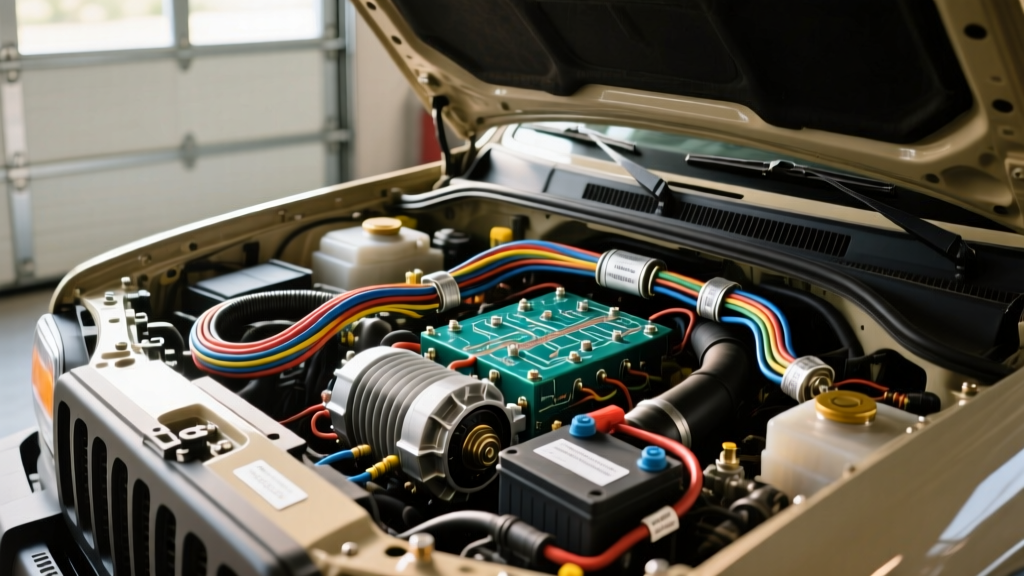
The Mission Auto Electric Philosophy: Mission-Critical Power
When building an expedition or overland vehicle, stock electrical architectures simply cannot sustain the parasitic draw of auxiliary lighting, winches, DC-DC chargers, and portable refrigeration. The 'mission auto electric' approach to vehicle modification is a benchmark methodology used by elite off-road fabricators. It prioritizes absolute redundancy, high-amperage headroom, and military-grade termination standards. A true mission auto electric overhaul ensures that a single chafed wire or corroded ground will not strand you in remote terrain. This guide details the exact technical specifications, wire gauges, and termination protocols required to execute a high-output, dual-battery electrical upgrade that meets expedition-grade reliability standards.
Phase 1: High-Output Alternator Integration
The foundation of any mission auto electric build is replacing the factory 130A-150A alternator with a 250A to 300A hairpin-style unit (such as a Denso or Power Bastards high-amp upgrade). Hairpin alternators offer superior efficiency at low RPMs, which is critical for off-road crawling and idling with heavy accessory loads.
Wiring and Termination Specifications
Upgrading the alternator output requires an immediate upgrade to the main charging wire. The factory 4 AWG or 6 AWG wire will melt under a sustained 250A load. You must upgrade to 1/0 AWG TXL (Thermoplastic Cross-Linked) primary wire. TXL wire features a thinner insulation wall compared to standard PVC, allowing for tighter bend radii in crowded engine bays while maintaining high heat resistance up to 125°C.
- Wire Gauge: 1/0 AWG TXL (Red insulation for 12V+ primary charge).
- Terminals: MIL-SPEC copper ring terminals, sized for M8 or 10-32 studs.
- Crimping: Use a 12-ton hydraulic crimper with hex-die jaws. Never use hammer-crimpers on 1/0 AWG wire; they create voids that lead to resistance and heat.
- Sealing: Apply 3:1 ratio adhesive-lined polyolefin heat shrink over the crimp barrel to prevent moisture ingress and galvanic corrosion.
Alternator B+ Terminal Torque
A common failure point in high-amp upgrades is a loose B+ terminal. The connection must be torqued to the manufacturer's specification—typically 10 to 12 Nm (89 to 106 in-lbs) for an M8 stud. Over-torquing will snap the internal rectifier diode stud, instantly destroying the alternator. Always use a backup wrench on the alternator casing nut to prevent the internal assembly from spinning.
Phase 2: Dual-Battery Isolation Architecture
A core tenet of the mission auto electric blueprint is separating the starting battery from the auxiliary 'house' battery bank. This ensures that running auxiliary loads (like a 12V fridge or camp lights) will never deplete the cranking battery.
Isolation Technology Comparison
| Technology | Efficiency | Complexity | Best Application |
|---|---|---|---|
| Standard Solenoid | Low (Voltage Drop) | Low | Budget winching setups |
| Diode Isolator | Medium (0.7V Drop) | Medium | Marine / Legacy RVs |
| ACR (Auto Charging Relay) | High | Medium | Standard Overland Dual-Battery |
| DC-DC Smart Charger | Maximum (100%) | High | Lithium (LiFePO4) Aux Banks |
For modern expedition rigs utilizing AGM or Lithium auxiliary batteries, a DC-DC Smart Charger (e.g., Redarc BTRS-1225S) is mandatory. Unlike a simple solenoid that connects the batteries in parallel, a DC-DC charger regulates the voltage profile to match the specific chemistry of the auxiliary battery, preventing overcharging and alternator burnout.
Sense Wire and Trigger Routing
When wiring an Automatic Charging Relay (ACR) like the Blue Sea Systems 7610, the ignition sense wire (typically 16 AWG Blue wire) must be connected to a true ignition-switched 12V+ source, not an accessory circuit that powers down during engine cranking. Use Deutsch DT series 2-pin connectors for all sense and trigger wire splices in the engine bay to guarantee a waterproof, vibration-proof seal.
Phase 3: Auxiliary Relay and Fuse Block Deployment
Centralizing auxiliary circuits into a dedicated fuse block eliminates the 'rat's nest' of inline fuses taped to the factory harness. The mission auto electric standard requires a sealed, bus-bar style fuse block (such as the Blue Sea Systems ST Blade) paired with a heavy-duty relay bank.
Standard Bosch ISO Mini Relay Pinout
Understanding the 5-pin Bosch ISO mini relay is critical for controlling high-draw accessories like LED light bars, air compressors, and radiator fans.
- Pin 30: 12V+ High-Current Input (Direct from fused bus-bar, typically 10 AWG).
- Pin 87: 12V+ High-Current Output (To the accessory load).
- Pin 85: Relay Coil Ground (Tied to a clean, bare-metal chassis ground).
- Pin 86: Relay Coil Trigger (12V+ from dashboard switch or ECU trigger, 16 AWG).
- Pin 87a: Normally Closed Output (Rarely used in automotive aux circuits; isolate with heat shrink).
Always use relays with integrated diodes or resistors across the coil (Pins 85 and 86) to suppress voltage spikes (back-EMF) that can fry sensitive ECU trigger circuits when the relay coil de-energizes.
Real-World Troubleshooting: Voltage Drop Testing
The ultimate validation of any mission auto electric project is the voltage drop test. According to SAE J1128 standards, a healthy 12V DC connection should exhibit a voltage drop of no more than 0.10V (100mV) across any single connection, splice, or switch under full load.
Testing Procedure
- Set your digital multimeter to DC Volts.
- Turn on the high-draw accessory (e.g., engage the winch or turn on the 200W LED light bar) to place the circuit under load.
- Place the red probe on the positive battery post and the black probe on the accessory's positive terminal. A reading higher than 0.50V indicates excessive resistance in the positive leg (undersized wire or poor crimps).
- Repeat for the ground side: Red probe on the accessory casing/ground terminal, black probe on the negative battery post.
If you detect a high voltage drop at a specific ring terminal, the issue is rarely the wire itself; it is almost always a contaminated mating surface. Remove the terminal, clean the chassis or bus-bar contact point with a wire brush down to bare, shiny metal, apply a thin layer of di-electric grease to the edges to prevent oxidation, and re-torque to 5-7 Nm.
Summary of Mission-Critical Best Practices
Executing a mission auto electric upgrade requires abandoning cheap, off-the-shelf automotive wire and terminals in favor of marine-grade and aerospace-grade components. By utilizing 1/0 AWG TXL wire, hydraulic hex-crimps, adhesive-lined heat shrink, and DC-DC smart isolation, you create an electrical architecture that can withstand the extreme vibrations, moisture, and thermal cycling inherent to severe off-road use. For further reading on circuit protection and bus-bar sizing, refer to the Blue Sea Systems Circuit Protection guidelines and the Painless Performance Wiring Manuals for advanced relay logic diagrams.