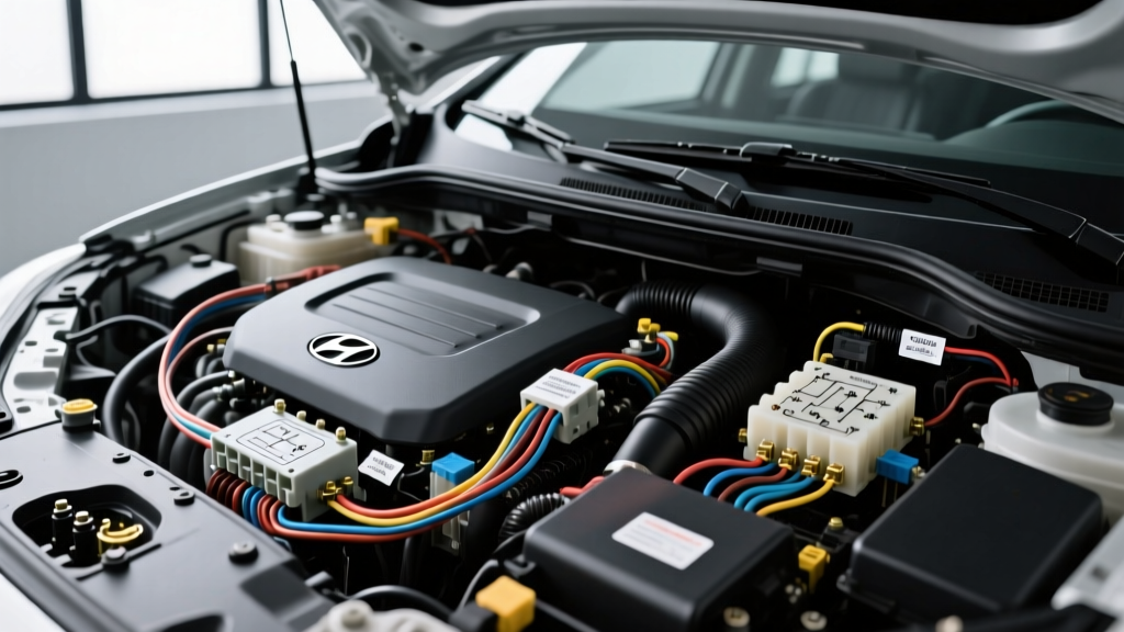
Hyundai Tucson Auto Electric Architecture Overview
The Hyundai Tucson (spanning the TL and NX4 platform generations) utilizes a highly multiplexed auto electric architecture designed to minimize wiring harness weight while maximizing module communication. At the core of this system is the Smart Junction Block (SJB) and the Integrated Power Supply (IPS) module, which act as the central gateways for power distribution and CAN bus routing. Understanding the specific wiring topologies, wire gauges, and communication protocols is critical for accurate diagnostics and aftermarket modifications.
Unlike older vehicles that relied on discrete, hardwired circuits for every accessory, the Tucson employs a Controller Area Network (CAN) split into high-speed powertrain domains (CAN-C at 500 kbps) and low-speed comfort/body domains (CAN-B at 125 kbps). According to SAE International J1939 standards, maintaining the 60-ohm terminating resistance across the CAN-H and CAN-L lines is vital to prevent signal reflection and module dropout.
Alternator and Charging System Specifications
The Tucson utilizes a LIN (Local Interconnect Network) controlled alternator, allowing the Engine Control Module (ECM) to dynamically adjust the voltage setpoint based on battery state-of-charge (SoC), electrical load, and ambient temperature. This reduces parasitic drag on the engine during high-load acceleration phases.
Alternator Connector (C134) Pinout Reference
The alternator is connected via a 3-pin connector. The B+ output terminal requires a 4 AWG cable routed directly to the IPS module or battery positive post. Below is the specific pin configuration for the 2.0L and 2.4L GDI engines:
| Pin | Function | Wire Color | AWG | Signal Description |
|---|---|---|---|---|
| 1 | LIN Bus | Green/White | 18 AWG | Digital communication to ECM for voltage regulation |
| 2 | FRM (Field Rate Monitor) | Yellow | 18 AWG | PWM signal to ECM indicating alternator load/duty cycle |
| 3 | IG (Ignition) | Black/Orange | 16 AWG | 12V reference from ignition switch to wake the regulator |
Diagnostic Note: If the LIN bus wire (Pin 1) experiences an open circuit, the alternator defaults to a fail-safe output of 13.8V. This often triggers a false battery warning light on the instrument cluster. Always verify LIN bus integrity using an oscilloscope; the signal should show a square wave oscillating between 1V and 12V.
Starter Motor Circuit & Voltage Drop Thresholds
The starter circuit in the Tucson is interlocked with the Inhibitor Switch (IMS), also known as the transmission range sensor, and the Smart Key module. The ECM grounds the starter relay coil only when it receives a valid 'Park' or 'Neutral' signal via CAN and a verified smart key authentication.
Starter Wiring and Torque Specifications
- B+ Terminal: 8mm stud, accepts 4 AWG or 2 AWG ring terminal. Torque specification: 10 - 12 Nm. Over-torquing can crack the internal solenoid bakelite housing.
- S Terminal (Solenoid Trigger): 12 AWG wire (typically Yellow or Black/White). Push-on spade connector. Voltage at this terminal during crank must not drop below 10.5V.
- Engine Ground Strap: Braided copper, 2 AWG equivalent. Connects the transmission bell housing to the chassis. Torque to 22 Nm.
When performing voltage drop testing on the starter circuit, the maximum allowable drop on the positive supply side (Battery Post to Starter B+) is 0.5V, and on the ground side (Starter Case to Battery Negative) is 0.2V. Exceeding these thresholds indicates high resistance in the IPS module internal busbars or corroded chassis grounds.
Electric AC Compressor (Hybrid & PHEV Tucson)
For technicians working on the Tucson Hybrid and Plug-in Hybrid (PHEV) variants, the auto electric landscape shifts dramatically with the introduction of the high-voltage electric AC compressor. Unlike belt-driven swashplate compressors, the Tucson hybrid utilizes a 270V DC inverter-driven scroll compressor.
High-Voltage HVAC Specifications
| Parameter | Specification |
|---|---|
| Operating Voltage | 240V - 310V DC (from Hybrid Battery) |
| Communication | LIN Bus to HVAC Control Module |
| Refrigerant Oil | ND-OIL 11 (POE - Polyol Ester) |
| Dielectric Strength | > 10^9 ohm-cm |
| Oil Capacity | 100 cc (System Total) |
Critical Warning: According to guidelines published by the Mobile Air Climate Systems Association (MACS), introducing standard PAG (Polyalkylene Glycol) oil into a Hyundai/Kia high-voltage electric compressor system will result in catastrophic inverter failure. PAG oil is highly conductive and will cause the internal 270V inverter to short to the compressor housing, triggering an isolation fault (DTC P0A09 or similar) and shutting down the entire high-voltage system.
Furthermore, the high-voltage orange cabling (typically 8 AWG or 6 AWG shielded cable) connecting the Hybrid Control Unit (HCU) to the compressor must be checked for shield grounding. The braided shield must be grounded at both ends to prevent Electromagnetic Interference (EMI) from disrupting the CAN-C powertrain network.
Fuse Box Layout and IPS Module Reference
The engine compartment Integrated Power Supply (IPS) module houses the high-amperage fuses and primary relays. Accessing these often requires removing the upper plastic cover and unclipping the side retaining tabs. Below are critical circuit references for the IPS module:
- EFI (Engine Fuel Injection): 20A Mini Fuse. Powers the ECM main relay and fuel pump relay coils. Wire color: Red/White.
- ABS Module Power (ABS1/ABS2): 40A and 30A Cartridge Fuses. Supplied directly from the B+ terminal block. Voltage drop here affects the ESC (Electronic Stability Control) initialization.
- MDPS (Motor Driven Power Steering): 80A or 100A Mega Fuse. The MDPS draws massive current (up to 60A under lock-to-lock load). Ensure the 6 AWG supply wire is free of green corrosion at the IPS terminal.
- Memory Fuse (Room Fuse): 10A. Located in the interior Smart Junction Block (SJB). Pulling this fuse prevents parasitic draw during long-term storage, but will reset the steering angle sensor (SAS) calibration, requiring a GDS (Global Diagnostic System) recalibration upon reconnection.
Network Topology and OBD2 Diagnostics
When interfacing with the Tucson's auto electric network via the Data Link Connector (DLC), technicians must adhere to strict pinout protocols to avoid module damage. The OBD2 port is located under the driver-side dash.
- Pin 6 (CAN-H): High-speed CAN bus. Idle voltage ~2.6V.
- Pin 14 (CAN-L): High-speed CAN bus. Idle voltage ~2.4V.
- Pin 3 (CAN-H) & Pin 11 (CAN-L): Medium/Low-speed Comfort CAN (Body, HVAC, SJB).
- Pin 16: Constant 12V Battery Power (20A fused).
For advanced module coding and bi-directional testing, reference the official Hyundai Tech Info portal to acquire the correct GDS software configurations and wiring schematics specific to the vehicle's exact VIN. Attempting to back-probe CAN bus wires with standard test light probes can pierce the wire insulation, leading to moisture ingress and eventual copper oxidation, which alters the characteristic impedance of the network and causes intermittent ghost faults.