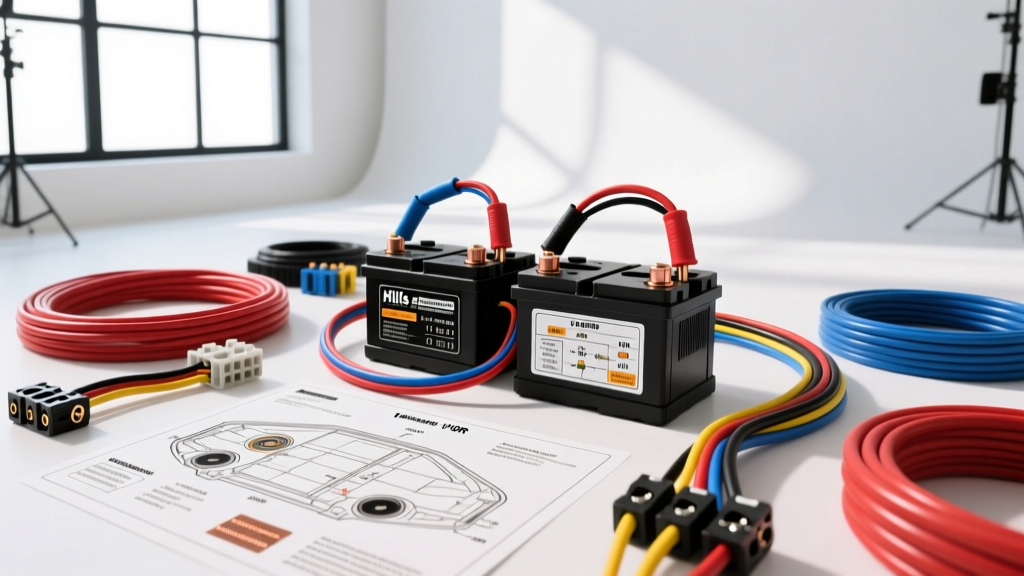
Introduction to the Hills Auto Electrical Methodology
When master technicians reference a 'Hills Auto Electrical' style diagram walkthrough, they are referring to a meticulous, node-by-node tracing methodology that prioritizes voltage drop mitigation, high-current isolation, and fail-safe grounding. Modern overland and commercial vehicles demand robust dual-battery architectures to support high-draw accessories like electric AC compressors, winches, and induction cooktops. A standard wiring schematic is rarely enough; you need a comprehensive walkthrough that bridges the gap between theoretical diagrams and physical harness routing.
In this guide, we will execute a complete wiring diagram walkthrough for a heavy-duty dual-battery system utilizing a 40A DC-DC charger and a 200A Voltage Sensitive Relay (VSR) backup. We will break down specific AWG requirements, connector pinouts, and torque specifications based on SAE J1128 Low Tension Primary Cable standards and industry-best practices for high-amperage automotive circuits.
Node 1: Alternator Output and Main Power Feed
The foundation of any dual-battery diagram begins at the alternator output terminal. Before routing a single wire, you must verify the alternator's maximum amperage. For a setup requiring a 40A DC-DC charger and a 150A continuous draw inverter, a minimum 180A alternator is required. If your vehicle is equipped with a smart alternator (variable voltage output), the wiring diagram must include an ignition-sense or CAN-bus bypass module to force the alternator into a high-output state (typically 14.4V to 14.8V).
Main Feed Wire Sizing and Protection
From the alternator B+ terminal (or the main starter battery positive post), the primary feed must be sized to handle the combined peak load plus a 20% safety margin. For a 200A peak circuit, Littelfuse MEGA fuse specifications dictate the use of 2/0 AWG wire for runs exceeding 10 feet to prevent excessive voltage drop. However, for standard engine bay runs under 5 feet, 1/0 AWG SXL (Cross-Linked Polyethylene) wire is sufficient.
- Wire Type: SXL or GXL (High-temperature resistance up to 125°C).
- Protection: 250A MEGA fuse mounted within 7 inches of the battery positive terminal.
- Termination: Heavy-duty closed-end ring terminals, crimped with a 12-ton hydraulic press and sealed with dual-wall heat shrink containing polyamide adhesive.
Node 2: DC-DC Charger and VSR Logic Pinouts
The core of the Hills Auto Electrical walkthrough focuses on the control logic of the charging nodes. Modern setups utilize a 40A DC-DC battery charger (such as a Redarc BCDC or CTEK D250) paired with a VSR for high-current accessory loads.
DC-DC Charger Connector Pinout Trace
The DC-DC charger typically utilizes a sealed 3-pin or 4-pin automotive connector (often a TE Superseal 1.5 series or equivalent Deutsch DT). Tracing this diagram requires strict adherence to the ignition sense circuit.
| Pin Number | Wire Color | AWG Size | Function & Routing Destination |
|---|---|---|---|
| Pin 1 | Red | 8 AWG | Main DC Input from Starter Battery (via 60A MIDI fuse) |
| Pin 2 | Black | 8 AWG | Chassis Ground (must share common ground bus bar) |
| Pin 3 | Blue | 16 AWG | Ignition Sense (tapped to an accessory circuit, e.g., wiper motor fuse) |
| Pin 4 | Yellow | 16 AWG | Solar Input (if applicable, routed to roof MC4 junction) |
Pro Tip: Never tap the ignition sense wire (Pin 3) directly to the ignition coil or fuel injector circuits. The inductive kickback from these circuits can fry the DC-DC charger's internal logic board. Always tap a low-draw accessory circuit and use a standard 30A automotive relay to isolate the sense signal if the circuit is PWM-controlled.
Node 3: High-Current Connector Matrix
Physical connections are the most common failure points in any auto electrical diagram. The Hills methodology mandates the use of Anderson Powerpole or Euro connectors for all removable high-current junctions. Below is the specification matrix for integrating these connectors into your auxiliary battery box.
Anderson SB175 and Powerpole 50A Integration
- Winch / High-Draw Node: Anderson SB175 (175A continuous). Use 2 AWG wire. The housing is genderless, but you must strictly follow the standard polarity molding to prevent catastrophic short circuits. Torque the internal set-screws to 4.5 Nm.
- Fridge / Accessory Node: APP (Anderson Powerpole) 50A grey housing. Use 6 AWG wire. Crimp the contacts using the specific Tri-Tool or Powerpole ratcheting crimper to ensure the retention spring is properly seated.
- Trailer Tow Node: If integrating a trailer charge line, use a 70A rated circuit with a 50A resettable circuit breaker mounted on the auxiliary battery side to protect the vehicle harness from trailer-side shorts.
Node 4: Grounding Architecture and Return Paths
A wiring diagram is only half the equation; the return path is where 90% of automotive electrical gremlins hide. The 'Hills Auto Electrical' standard strictly forbids daisy-chaining grounds. Every high-current node must have a dedicated, star-wired return path to a centralized ground bus bar, which is then tied to the chassis and engine block.
Chassis Ground Preparation and Torque Specs
When terminating an 8 AWG or larger ground wire to the vehicle chassis, follow this exact preparation sequence:
- Drill a hole for an M8 or M10 stainless steel or zinc-plated bolt.
- Use a 3M Scotch-Brite pad or sandpaper (120 grit) to remove all paint, powder coat, and primer down to bare, shiny metal. The contact area must be 20% larger than the ring terminal footprint.
- Apply a thin layer of dielectric grease after tightening to prevent oxidation, but never apply it before, as it acts as an insulator and increases resistance.
- Use a star washer (internal tooth) between the ring terminal and the chassis to bite through any microscopic corrosion.
- Torque the M8 bolt to 15 Nm (11 lb-ft) and the M10 bolt to 25 Nm (18 lb-ft). Over-torquing will stretch the bolt and reduce clamping force over thermal cycles.
Node 5: Voltage Drop Testing and Troubleshooting
Once the physical wiring matches the diagram, you must validate the circuit using voltage drop testing. According to Haynes automotive wiring fundamentals, a healthy high-current circuit should exhibit a total voltage drop of no more than 0.2V across the entire positive and negative loop under maximum load.
Diagnostic Decision Tree
- Symptom: DC-DC charger drops out intermittently under load.
Cause: Voltage drop on the ignition sense wire or main feed.
Fix: Place multimeter probes on the battery post and the DC-DC input terminal. If the drop exceeds 0.3V under a 40A load, upgrade the 8 AWG feed to 6 AWG or clean the MIDI fuse contacts. - Symptom: VSR clicks rapidly (chattering) when the engine is idling.
Cause: Smart alternator dropping voltage below 13.3V at idle, causing the VSR to disengage and re-engage.
Fix: Install a smart alternator override module or replace the VSR with a solid-state battery isolator that utilizes a time-delay hysteresis circuit. - Symptom: Anderson plug housing shows signs of melting.
Cause: Improper crimping causing high resistance at the terminal-to-wire interface.
Fix: Cut back the wire, strip fresh insulation, and re-crimp using a calibrated ratcheting crimper. Verify the wire gauge matches the terminal barrel size exactly (e.g., do not use 4 AWG wire in a 2 AWG terminal without reducing pins).
Conclusion
Executing a complete wiring diagram walkthrough requires more than just connecting positive to positive and negative to negative. By adhering to the rigorous standards outlined above—referencing SAE cable specifications, utilizing proper hydraulic crimping, and enforcing strict voltage drop limits—you ensure your dual-battery system will withstand the harsh thermal and vibrational environments of automotive applications. Whether you are wiring an electric AC compressor, a heavy-duty winch, or a remote camp setup, this methodology guarantees reliable, safe, and efficient power delivery.