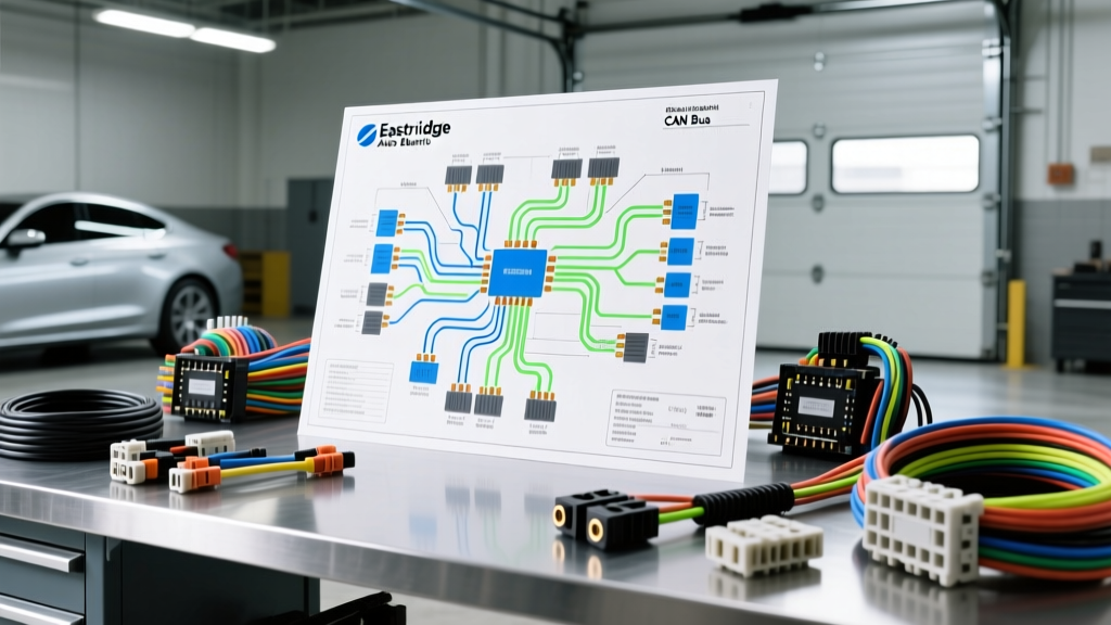
The Eastridge Auto Electric Approach to Modern Vehicle Architecture
When diagnosing complex multiplexed networks and high-amperage charging systems, generic repair manuals and basic scan tools inevitably fall short. Top-tier diagnostic methodologies, often associated with premier regional specialists and advanced training centers like Eastridge Auto Electric, rely on empirical waveform analysis, strict voltage drop thresholds, and an intimate understanding of OEM network topologies. Modern vehicles are essentially rolling data centers, utilizing Controller Area Network (CAN) buses, LIN (Local Interconnect Network) buses, and FlexRay architectures to manage everything from powertrain telemetry to advanced driver-assistance systems (ADAS). This advanced technical deep dive explores the rigorous diagnostic protocols required to isolate electrical faults that standard OBD2 code readers simply cannot detect, ensuring that technicians approach every electrical anomaly with surgical precision.
Advanced CAN Bus Topology and Termination Testing
High-speed CAN (ISO 11898-2) is the undisputed backbone of modern powertrain and chassis communication. A fundamental step in the Eastridge Auto Electric diagnostic protocol is verifying network integrity at the physical layer before condemning any control module. The network relies on a twisted-pair architecture—typically twisted at a rate of one twist per inch to reject electromagnetic interference (EMI)—terminating at both ends of the bus with 120-ohm resistors.
Standard High-Speed CAN C Voltage Specifications
When measuring CAN bus voltages with a high-impedance digital multimeter (DMM) or a PicoScope, technicians must observe the differential voltage states. The recessive and dominant states dictate the logic level of the network. Because the DMM averages the rapid voltage transitions, the readings will appear as steady DC voltages, whereas an oscilloscope will reveal the actual square-wave digital communication.
| Parameter | CAN High (CAN-H) | CAN Low (CAN-L) | Differential Voltage |
|---|---|---|---|
| Recessive State (Logic 0) | 2.50V | 2.50V | 0.00V |
| Dominant State (Logic 1) | 3.50V | 1.50V | 2.00V |
| Termination Resistance | 60 ohms (measured across CAN-H and CAN-L with battery disconnected) | ||
If a DMM reads exactly 120 ohms, one terminating resistor (usually located inside the PCM, BCM, or a central gateway module) is missing, or the bus is severed. A reading of 40 ohms indicates an aftermarket module with an internal 120-ohm resistor was improperly spliced into the network, creating a parallel resistance fault that will eventually corrupt data packets. For GM High-Speed GMLAN applications, expect CAN-H to be Dark Green and CAN-L to be Dark Blue. For Ford MS-CAN, CAN-H is typically White/Blue and CAN-L is White/Brown. Always consult OEM wiring schematics, as detailed in the SAE J2284 High-Speed CAN Standard, to verify pinouts at the Data Link Connector (DLC). Pins 6 and 14 are universally reserved for High-Speed CAN-H and CAN-L, respectively.
Alternator Ripple Voltage and Diode Rectifier Testing
A frequently overlooked aspect of advanced auto electrical diagnostics is the quality of the DC voltage produced by the alternator. The internal stator generates three-phase AC voltage, which is converted to DC by a diode rectifier bridge. If a single diode fails open or shorted, the alternator will still charge, but it will introduce excessive AC ripple into the vehicle's electrical system. This ripple can confuse sensitive logic boards, cause erratic sensor readings, and degrade battery life.
The Eastridge Auto Electric methodology requires measuring AC ripple voltage at the battery posts with the engine running at 2,000 RPM and all major electrical loads (HVAC, headlights, rear defroster) activated. A healthy alternator should produce less than 50mV (0.050V) of AC ripple. If the AC ripple exceeds 100mV, the diode rectifier assembly is compromised. Technicians must ensure their DMM is set to AC Volts (mV range) and use shielded test leads to prevent the alternator's own electromagnetic field from inducing false readings in the test leads.
High-Amperage Circuit Voltage Drop Protocols
While network diagnostics require oscilloscopes and logic analyzers, the foundation of auto electric repair remains deeply rooted in Ohm's Law. High-amperage circuits—such as the starter motor, alternator B+ feed, and high-current electric cooling fans—suffer from hidden resistance that a standard continuity test will never reveal. A wire with only two strands of copper remaining out of fifty will show continuity (near 0 ohms) on a multimeter, but will catastrophically fail under a 150-amp starter load. The Eastridge Auto Electric methodology mandates dynamic voltage drop testing under load.
Starter Circuit Voltage Drop Decision Tree
A failing starter is frequently misdiagnosed when the actual fault lies in degraded battery cables, corroded ground straps, or loose buss bar connections. Perform the following voltage drop tests with the engine cranking. (Note: Disable fuel injection or use a remote starter switch to prevent the engine from firing if testing for extended durations).
- Positive Side Test: Place the DMM red lead directly on the battery positive post (not the lead clamp) and the black lead on the starter B+ terminal. Crank the engine. Specification: Maximum 0.50V drop across the entire positive cable assembly. (Ideally < 0.20V for heavy-duty and diesel applications).
- Control Circuit Test: Place the red lead on the battery positive post and the black lead on the starter solenoid 'S' or '50' control terminal. Crank the engine. Specification: Maximum 0.30V drop through the ignition switch, relays, and neutral safety switch.
- Ground Side Test: Place the red lead on the starter housing (clean, unpainted metal) and the black lead directly on the battery negative post. Crank the engine. Specification: Maximum 0.20V drop.
If the ground side exceeds 0.20V, the engine block ground strap or the battery-to-chassis cable is compromised. Never replace a starter or battery without verifying these three voltage drops. For advanced waveform analysis of starter current draw, refer to the Pico Technology Automotive Waveform Library, which provides baseline amp-clamp signatures to identify shorted armature coils or worn bushings based on current spikes.
Parasitic Draw: Beyond the Standard Multimeter
Modern luxury and late-model domestic vehicles feature complex sleep-cycle architectures. Modules like the Telematics Gateway, Body Control Module (BCM), and infotainment systems can take up to 45 minutes to enter a low-power sleep state. Connecting a standard DMM in series to measure parasitic draw often requires opening a door, depressing the latch, or waking the network, which resets the sleep timer and leads to false diagnoses of high draw.
The advanced protocol utilizes a low-amp current clamp (e.g., Pico TA018 or Fluke i410) paired with an oscilloscope or data-logging multimeter. This allows the technician to monitor the draw continuously without breaking the circuit. Breaking the circuit with a DMM introduces a voltage drop across the meter's internal shunt (often up to 200mV), which can inadvertently keep sensitive modules awake or trigger brown-out resets.
OEM Parasitic Draw Thresholds and Fuse Voltage Drop
| Vehicle Architecture | Typical Sleep Time | Target Parasitic Draw |
|---|---|---|
| Standard Domestic (FCA/GM/Ford) | 10 - 20 Minutes | < 30mA (0.030A) |
| European Luxury (BMW/Audi/Porsche) | 30 - 45 Minutes | < 40mA (0.040A) |
| Hybrid/EV Architectures | 15 - 60 Minutes | < 20mA (0.020A) (12V Aux System) |
When a draw exceeds 50mA after the sleep cycle, the isolation process involves identifying the offending circuit without pulling fuses. Pulling a fuse breaks the circuit and wakes the bus. Instead, utilize the milli-volt drop method across the fuse. Set your DMM to the millivolt DC scale and probe the two test points on the top of the mini/ATO fuse while the circuit is under load. Using a standardized fuse voltage drop chart (correlating mV drop to amperage based on the fuse's specific resistance), you can pinpoint the exact circuit drawing current without ever interrupting the network's sleep state.
Reference Chart: OEM Wire Gauge vs. Aftermarket AWG
When repairing severed harnesses, installing electric AC compressors, or upgrading alternator output, matching the correct American Wire Gauge (AWG) is critical. Many OEM harnesses use metric cross-sectional areas (mm²). Splicing an 8 AWG wire into a 4.0 mm² OEM circuit creates a bottleneck and a potential fire hazard. The following conversion chart is essential for proper harness repair and adheres to industry best practices.
| OEM Metric (mm²) | Equivalent AWG Size | Max Amperage (Chassis Wiring) | Common Application |
|---|---|---|---|
| 0.5 mm² | 20 AWG | 5A | CAN Bus, Sensor Signals |
| 1.0 mm² | 16 AWG | 10A | Lighting, Relay Coils |
| 2.5 mm² | 12 AWG | 20A | Fuel Pump, Power Windows |
| 4.0 mm² | 10 AWG | 30A | Cooling Fans, ABS Valves |
| 10.0 mm² | 6 AWG | 60A | Alternator B+ Feed |
| 25.0 mm² | 2 AWG | 150A+ | Battery to Starter Cable |
Always use adhesive-lined heat shrink (dual-wall) with a 3:1 shrink ratio for any harness repair to ensure a moisture-tight seal, preventing capillary action from drawing water into the connector cavities. Never use twist-on connectors or electrical tape for under-hood harness repairs. For comprehensive guidelines on automotive wiring standards, insulation types, and crimping specifications, consult the SAE J1128 Low Tension Primary Cable Standard.
Conclusion: Precision Over Parts Swapping
The diagnostic philosophy championed by top-tier specialists and embodied in the Eastridge Auto Electric methodology proves that modern auto electrical repair is an exact, unforgiving science. By leveraging oscilloscope waveform analysis, strict voltage drop limits, non-intrusive parasitic draw testing, and precise metric-to-AWG conversions, technicians can accurately pinpoint faults in complex multiplexed networks and high-amperage circuits. Mastering these advanced protocols ensures lasting repairs, prevents collateral damage to sensitive control modules, and eliminates the costly parts swapping approach that continues to plague the automotive repair industry.